ALL-SPEC_Unit_HON.doc 07/2011
7/9
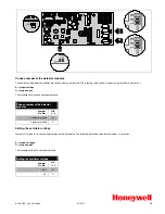
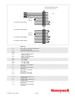
X6
0V
+24V
9
8
7
6
5
4
3
2
1
1
2
3
4
5
6
7
8
9
internal connection base board
9
8
6
11
_
+
24 V
_
+
_
+
DJ 1191
or
DJ 1192
0V
+24V
X7
1
2
3
4
5
6
7
8
9
_
+
connection to central fire panel
DJ 1191
or
DJ 1192
2
1
7
6
5
4
3
connection to central fire panel
connection to central fire panel
connection to central fire panel
Connection
X6, 1
X6, 2
X6, 3
contact of the first alarm relay (make contact)
centre tap of first alarm relay
contact of the first alarm relay (break contact)
X6, 4
X6, 5
+ external response indicator for
first detector module
– external response indicator for
first detector module
X6, 6
X6, 7
+ 24 V reset input
0 V reset input
X6, 8
X6, 9
+ 24 V supply voltage
0 V supply voltage
X7, 1
X7, 2
fault contact 2
nd
detector module
(connection 1)
fault contact 2
nd
detector module
(connection 2)
X7,3
X7, 4
X7, 5
contact of the 2
nd
alarm relay
(make contact)
centre tap of 2
nd
alarm relay
contact of the 2
nd
alarm relay
X7, 6
X7, 7
+ external response indicator for 2
nd
detector module
– external response indicator for 2
nd
detector module
X7, 8
X7, 9
fault contact first detector module
(connection 1)
fault contact first detector module
(connection 2)

