ALL-SPEC_Unit_HON.doc 07/2011
2/9
Installation of the Detector Module
Please note:
Only the detector modules of the type ASD-TP-05, ASD-TP-01 and ASD-TP-001 that have been approved by the VdS-certification authority with the
approval number G 202064 may be used.
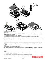
1. Carry out the following works only if the device is powered down.
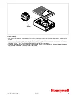
2. Open the device by carefully unlocking the housing snap-in closures by means of a screwdriver. Then lift the housing lid a little bit.
3. Carefully pull the connection cable of the display board off and remove the housing lid.
Note:
Shall the device only be provided with one detector module, please skip to point 6. Shall the device however be provided with two modules please
follow the following instructions.
4. If you want to install a second detector module you have to recover carefully the ventilator cover for the second air sampling duct (self-adhesive
plastic cover). Take for this if necessary a screwdriver.
5. Break carefully the clasp for the connection of the second pipe system (predetermined breaking point, marked by “II“) with a screwdriver from the
housing.
Note:
The knocked clasp is to removed completely from the device.
6.
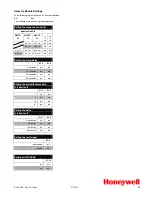
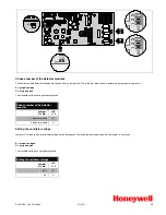
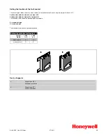
Make the required settings at the detector module by setting the contacts of switch S1 accordingly (see also “Settings of the detector module”).
7.
Carefully spread a bit the support clamps used to fix the detector module in the corresponding mounting position.
8.
Carefully place the detector module in between them until it audibly snaps in and thus is fixed by the support clamps.
Note:
Make sure that the inserted detection module is fixed tight and save by the brackets by pressing the brackets additional by hand.
9.
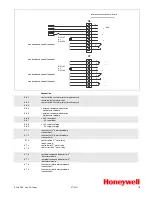
Connect the detector module via the ribbon cable with the connection “Head 1” (detector module I) or “Head 2” (detector module II) to the base
board. Note the labelling of the base board.
10. Reconnect the display board to the base board. Note the connections and labelling of the base board.
9
O
F
F
S1
8
10
7
6
5
8
4
4

