Honeywell ADEMCO VISTA 10P Installation Manual Download Page 6

6

STEP 3: 

ENABLE KEYPAD ADDRESS

ENABLING KEYPAD 8 DEVICE ADDRESS 23

The SEM communicates with the VISTA panel as if it is a keypad.  
By default, the SEM will use 

Keypad 8 Device Address 23

 to 

communicate. Address 23 must be enabled via panel programming.  
To do this, enter programming and select 

*196 + [1] + *99

 at the keypad.

IF ADDRESS 23 IS ALREADY IN USE

In most cases, Address 23 will be available. If another keypad is already 
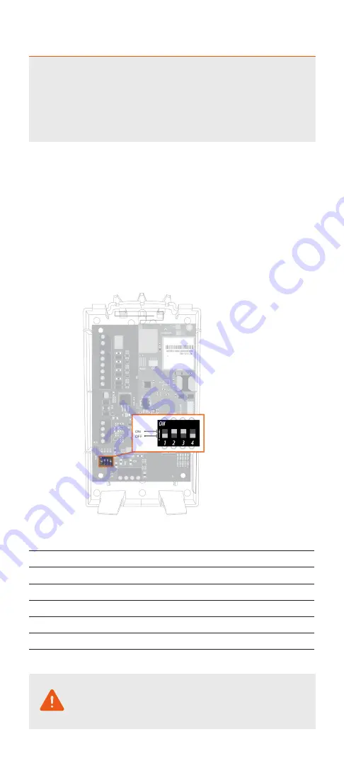
connected to Address 23, you will need to manually select a different 
keypad address. You can do this by using the DIP switches on the SEM,  
as pictured below.

1. 

Identify an available keypad address.

2. 

Using the chart below, change the DIP switches on  
the SEM to match the corresponding keypad address.

3. 

Enable the address by entering the corresponding  
VISTA programming command at the panel.

If the correct keypad address is not enabled, repeated 
reports of Panel Malfunction will be shown in the Event 
History on the Partner Portal or MobileTech once the 
SEM is powered on and connects to the network.

Keypad  

Address

DIP Switch  

Setting

VISTA  

Programming Menu

17

None—all OFF

*190

18

Switch 4 ON, others OFF

*191

19

Switch 3 ON, others OFF

*192

20

Switch 3 and 4 ON, others OFF

*193

21

Switch 2 ON, others OFF

*194

22

Switch 2 and 4 ON, others OFF

*195

23

Switch 2 and 3 ON, others OFF

*196

Summary of Contents for ADEMCO VISTA 10P

Page 1: ...SYSTEM ENHANCEMENT MODULE Honeywell ADEMCO VISTA INSTALLATION GUIDE INSTALL WIZARD AVAILABLE AT ALARM COM SEMVISTA DUAL PATH ...

Page 2: ... and optional broadband Ethernet The SEM is intended to be used as the primary communication path for all alarm signaling to the central monitoring station The wireless alarm signaling and routing service is operated by Alarm com The SEM also features integrated support for Alarm com s home automation services with built in Z Wave capabilities Alarm com strongly recommends installing an alpha keyp...

Page 3: ...Address 6 Step 4 Disconnect Power from Panel 7 Step 5 Mount the SEM 8 Step 6 Wire the SEM to the VISTA Panel 9 Step 7 Power Up the Panel 10 Add Delete Z Wave Devices 11 Touchscreen Keypads 14 Panel Settings 15 LEDs 16 FAQs 19 Troubleshooting 21 Specifications 22 Regulatory Information 23 SEM Quick Tips 24 ...

Page 4: ...st Alert FA148CP First Alert FA148CPSIA Honeywell ADEMCO VISTA 20P Honeywell ADEMCO VISTA 20PSIA First Alert FA168CPS First Alert FA168CPSSIA Please see the Alarm com Partner Portal Knowledge Base www alarm com dealer for the most up to date list of compatible panels TOUCHSCREEN KEYPADS Touchscreen keypad compatibility details can be found on page 14 Some system changes will not be processed by Al...

Page 5: ...he account Customer Address Customer Phone Number Customer Email Address Preferred Login Name for the Customer Alarm com Module Serial Number Existing Panel Installer Code During Step 4 of the Create New Customer process you will be prompted to enter the current Installer Code on the panel Alarm com will use this code to access panel programming and read information stored on the panel At the end ...

Page 6: ... on the SEM as pictured below 1 Identify an available keypad address 2 Using the chart below change the DIP switches on the SEM to match the corresponding keypad address 3 Enable the address by entering the corresponding VISTA programming command at the panel If the correct keypad address is not enabled repeated reports of Panel Malfunction will be shown in the Event History on the Partner Portal ...

Page 7: ...L Prior to disconnecting power from the panel first verify that the panel is disarmed Next remove panel AC Power and disconnect the backup battery This is necessary to prevent damaging the panel or module while making wiring connections ...

Page 8: ...set it aside Carefully remove the SEM circuit board by depressing the interior bottom tab Place the SEM back plate on the wall at the desired mounting location and mark the three mounting holes as shown below Set the back plate aside and drill holes at the mounting locations Use wall anchors where studs are not present and secure the back plate to the wall with the enclosed screws Insert the SEM c...

Page 9: ...ery connector to connect the battery to both the SEM and the panel For a power limited circuit ensure the fuse is inside the VISTA panel Once wiring is complete route the antenna s outside of the enclosure away from the SEM and replace the enclosure cover Please note that the antenna s should be routed through the second and third channel openings at the top of the enclosure see zoom view below 12...

Page 10: ...e the keypad will display the home screen This process will take less than 3 minutes Now that the zone scan is complete the Equipment list should be updated on the Partner Portal and the Installer and Master User codes should be synced with the SEM ZONE SCAN COMPLETE Ready to Arm If you do not see the MODEM COMM message appear on the keypad during zone scan and instead notice the keypad scrolling ...

Page 11: ...evices to their final location on the property 2 Log in to MobileTech 3 Find the customer account 4 Tap Equipment 5 Tap Z Wave Devices 6 Tap to expand Z Wave Actions 7 Tap Add Z Wave Devices 8 Wait for the bolded message Checking for new devices on the network 9 Trigger a device to add it to the network 10 When a device is added successfully it shows up on this screen following a 30 second delay 1...

Page 12: ...customer account 3 Tap Equipment 4 Tap Z Wave Devices 5 Tap to expand Z Wave Actions 6 Tap Delete Z Wave Devices 7 Wait for the bolded message Checking for deleted devices on the network 8 Trigger a device to delete it from the network 9 When a device is deleted successfully and its network data is erased it will show up on this screen following a 30 second delay 10 Continue triggering devices You...

Page 13: ...0 second delay 9 Continue triggering devices You may delete several devices from the network without re entering Delete Mode To delete Z Wave devices using the SEM 1 Press and hold the Z Wave button on the Alarm com module 2 Release the button after LED L5 flashes in groups of two L2 also flashes 3 Press and hold the Z Wave button on the module a second time 4 Release the Z Wave button after LED L...

Page 14: ... Z Wave automation via Alarm com only This means that customers using the Tuxedo Touch to control their Z Wave devices will need to choose whether to continue using the Tuxedo Touch for Z Wave automation or whether to switch to Alarm com for example automation control using the Customer Website Mobile App and intelligent automation rules If the customer chooses to switch to Alarm com Z Wave contro...

Page 15: ...o be set to a four digit number Alarm com automatically set this setting to 1234 45 Partition 2 Primary Acct No needs to be set to a four digit number Alarm com automatically set this setting to 4321 48 Report Format needs the primary phone number format set to 77 55 Dynamic Signaling Priority needs to be set to 1 64 Test Report Code needs to be set to 1 0 92 Phone Line Monitor Enable needs to be ...

Page 16: ...e installation resources L6 Reserved for future use L7 Reserved for future use LED L1 RED L1 flashes when an error is encountered The number of flashes indicates the error number If there are two or more errors at the same time the errors will flash one after the other The LED will stay off for at least four seconds between errors NUMBER OF LED L1 ERROR DESCRIPTIONS AND SOLUTION FLASHES 1 Alarm co...

Page 17: ...e normal pattern calls for a series of quick flashes every two seconds when the Alarm com module is in Idle mode or four seconds in PowerSave mode See Alarm com Module States modes for an explanation of the three modes L2 also occasionally flashes in patterns to indicate Z Wave status when the SEM is being used to add or remove Z Wave devices LED L3 GREEN OR YELLOW L3 flashes with every communicat...

Page 18: ...ule just powered up AC power is down or battery level is less than 11 5 volts The radio part of the SEM draws 10 mA in PowerSave mode It is fully functional and will go into Connected mode as soon as a signal needs to be sent Performing an Alarm com phone test will switch the module into Idle mode and update the signal level reading L1 Inactive L2 Communication with panel L3 Same flashing pattern ...

Page 19: ... areas with excessive metal or electrical wiring such as furnace or utility rooms Mount the module near an outside wall preferably on an upper level Do not mount the SEM inside of the panel s metal box Doing so will negatively impact Z Wave performance For homes or businesses located in canyons or with hills nearby it may be necessary to place the antenna higher in the building If the SEM location...

Page 20: ...l 2 Disconnect the touchscreen keypad or AUI device from the panel 3 Install the SEM following the SEM installation steps without the touchscreen keypad or AUI device connected 4 Once the SEM is installed and working properly power down the system 5 Reconnect the touchscreen keypad or AUI device 6 Restore power to the panel and SEM Does the SEM support multiple partitions The SEM does support part...

Page 21: ...from the panel and verify that all wiring is correct My panel changed from ARM AWAY to ARM STAY automatically Auto Arm Stay is enabled by default on the VISTA panel If enabled the panel will change from ARM AWAY to ARM STAY if a sensor is not opened and closed during the exit delay This arming status will then be updated on the Customer Website and Mobile App This setting can be disabled using the...

Page 22: ...erminal keypad bus 12V power and ground to panel battery Alarm com Module Indicators One module panel communication status LED one module power LED one automation LED three wireless communication status LEDs SEM Circuit Board Indicators One LAN LED one processor LED one COMM fail LED Operating Temperature 32 to 120 F 0 to 49 C Storage Temperature 30 to 140 F 34 to 60 C Humidity 90 relative humidit...

Page 23: ...a circuit different form that which the receiver is connected Consult the dealer or an experienced radio TV technician for help Operation is subject to the following two conditions 1 This device may not cause interference 2 This device must accept any interference including interference that may cause undesired operation of the device This equipment complies with the FCC RF radiation exposure limi...

Page 24: ...m still fails to initiate a zone scan set the Installer Code to a new value and power cycle If the customer has existing Z Wave devices they will need to be deleted from the previous controller and added to the SEM Tuxedo Touch users will need to choose between leaving devices enrolled on the Tuxedo for local control or enrolling them on the SEM to enable remote control capability CONTACT INFORMAT...

Reviews: