background image

6/99

9782 Series Conductivity/Resistivity Analyzer/Controller - Operator’s Manual

xi

Tables

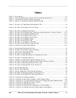
Table 1-1  Key Functions .......................................................................................................................... 1-6
Table 1-2  9782 Conductivity/Resistivity Analyzer/Controller Menu Hierarchy................................... 1-11
Table 1-3  Available Combinations of Relay Assigments ...................................................................... 1-15
Table 1-4  Overview of Analyzer/Controller Installation Tasks............................................................. 1-17

Table 3-1  Procedure for Unpacking and Preparing the 9782................................................................... 3-2

Table 4-1  Procedure for Installing AC Power Wiring ............................................................................. 4-4

Table 5-1  Procedure for Performing I/O Setup ........................................................................................ 5-6
Table 5-2  Procedure for Configuring CAT Control and/or Retransmission of Process Variables........ 5-10
Table 5-3  Procedure for Configuring On/Off Control ........................................................................... 5-13
Table 5-4  Procedure for Configuring PFT Control ................................................................................ 5-14
Table 5-5  Procedure for Configuring DAT Control............................................................................... 5-15
Table 5-6  Procedure for Configuring Alarms ........................................................................................ 5-16
Table 5-7  Procedure for Setting the Clock............................................................................................. 5-17
Table 5-8  Procedure for Configuring AutoClean................................................................................... 5-19
Table 5-9  Procedure for Specifying a Computed Value ........................................................................ 5-21
Table 5-10  Menu Choices and System Defaults .................................................................................... 5-23

Table 6-1  Recommended Maximum Wire Size ....................................................................................... 6-3
Table 6-2  Procedure for Installing Analog I/O Wiring ............................................................................ 6-5
Table 6-3  Relay Contact Maximum Ratings ............................................................................................ 6-7
Table 6-4  Procedure for Wiring Relays ................................................................................................... 6-8
Table 6-5  Procedure for Disconnecting RC Arc Suppression Circuits.................................................... 6-9

Table 8-1  Procedure for Entering Cal Factor ........................................................................................... 8-4
Table 8-2  Conductivity of Potassium Chloride Solutions at 25 

°

C ......................................................... 8-5

Table 8-3  Procedure for Performing Calibration Trim Using a Reference Solution ............................... 8-6
Table 8-4  Procedure for Removing Calibration Trim Values.................................................................. 8-7
Table 8-5  Procedure for Entering TDS Conversion Factor...................................................................... 8-9

Table 9-1  System Status Message ............................................................................................................ 9-2
Table 9-2  Process Alarm Messages.......................................................................................................... 9-3
Table 9-3  On-Line Diagnostics and System Error Messages................................................................... 9-4
Table 9-4  Procedure For Initiating Display and Keyboard Tests............................................................. 9-5
Table 9-5  Procedure for Testing Relays and Analog Outputs ................................................................. 9-7

Table 10-1  Procedure for Calibrating Outputs....................................................................................... 10-4
Table 10-2  Procedure for Specifying a Tagname or Other Display String ............................................ 10-6
Table 10-3  Procedure for Viewing Product Information and  Changing the Stored Model Number .... 10-7
Table 10-4  Procedure for Adjusting the Screen Contrast ...................................................................... 10-9
Table 10-5  Procedure for Entering a Password.................................................................................... 10-10
Table 10-6  Procedure for Resetting All Configuration to Factory Settings......................................... 10-11
Table 10-7  Procedure for Entering Values for Lead Resistance Compensation.................................. 10-14

Summary of Contents for 9782 Series

Page 1: ...9782 Series Two Cell Conductivity Resistivity Analyzer Controller Operator s Manual 70 82 25 74 Rev 3 6 99 ...

Page 2: ... ATTENTION The emission limits of EN 50081 2 are designed to provide reasonable protection against harmful interference when this equipment is operated in an industrial environment Operation of this equipment in a residential area may cause harmful interference This equipment generates uses and can radiate radio frequency energy and may cause interference to radio and television reception when the...

Page 3: ...9 to reflect changes in the software 2 12 98 Included dimension drawings for backlit and non backlit option Sec 3 3 6 99 Edits were made to standardize terminology and to add the latest MSG References Honeywell Documents The following list identifies all Honeywell documents that may be sources of reference for the material discussed in this publication Document Title ID Binder Title Binder ID Trad...

Page 4: ...ameter for edit 1 7 Editing a parameter assignment from a list of available choices 1 7 Editing a parameter numeric value 1 7 Controlling an AutoClean operation manually 1 7 1 3 2 Online Displays 1 8 Introduction 1 8 Individual cell display 1 8 Combined display 1 9 Computed value 1 9 Clock and AutoClean 1 10 1 4 Menu Hierarchy 1 11 Menus for every task 1 11 1 5 Planning 1 13 1 5 1 Overview 1 13 Co...

Page 5: ...nder reference operating conditions 2 4 Operating Influences under normal operating conditions 2 4 2 1 7 Outputs 2 4 Standard alarm control relays 2 4 Optional alarm control relays 2 4 Optional analog outputs 2 4 Optional Digital Communication Link 2 5 2 1 8 Temperature Compensation 2 5 Availability 2 5 2 1 9 AutoClean 2 5 Cell rinse schedule settings 2 5 2 1 10 Control 2 5 Settings 2 5 2 1 11 Com...

Page 6: ...yzer Controller 5 1 5 2 I O Setup and Configuration Tasks 5 2 Ease of configuration 5 2 Accessing the I O setup and configuration menus 5 2 Purpose of I O setup 5 2 Purpose of configuration menu items 5 2 Illustrations 5 3 System defaults 5 3 5 3 Performing I O Setup 5 4 Purpose 5 4 Display resolution and unit of measure 5 4 5 4 Configuring Current Adjusting Type CAT Control and or Retransmission ...

Page 7: ...e 6 3 Shielded wiring for locations with interference 6 3 Avoiding interference 6 3 References 6 3 6 3 Wiring Analog Inputs and Outputs 6 4 Introduction 6 4 Cell identification significant to computed value 6 4 Procedure 6 4 6 4 Wiring Relays 6 7 6 4 1 Installation 6 7 Introduction 6 7 Procedure 6 7 6 4 2 Disconnecting RC Arc Suppression Circuits 6 9 Introduction 6 9 Procedure 6 9 6 4 3 Wiring a D...

Page 8: ... 8 7 8 6 Determining and Entering the TDS Conversion Factor 8 8 Introduction 8 8 Determining TDS conversion factor 8 8 Out of range values forced to closest limit 8 8 Calibrate the Analyzer Controller before entering TDS conversion factor 8 8 Procedure 8 9 9 DIAGNOSTICS AND MESSAGES 9 1 9 1 Overview 9 1 Introduction 9 1 What s in this section 9 1 9 2 System Status Messages 9 2 Related to operation...

Page 9: ... Procedure 10 9 10 6 Entering a Password for Security 10 10 Introduction 10 10 Procedure 10 10 10 7 Resetting All Configuration and Calibration Values to Factory Settings 10 11 Introduction 10 11 Procedure 10 11 10 8 Entering Values for Lead Resistance Compensation Wide Range Only 10 12 Introduction 10 12 Procedure 10 14 10 9 Replacing the Fuse 10 15 Introduction 10 15 Procedure 10 15 11 ACCESSORI...

Page 10: ...Measurements B 3 Sodium Hydroxide Hydrochloric Acid Concentration Measurements B 4 APPENDIX C MICROPROCESSOR BOARD SWITCH SETTINGS C 1 Introduction C 1 Location of switches C 1 SW1 all positions set to off C 1 SW2 settings are dependent on options C 1 APPENDIX D USING A PRECISION CHECK RESISTOR D 1 Introduction D 1 Set cal factor and calibration trim for ideal conditions D 1 Calculations for condu...

Page 11: ... for Installing Analog I O Wiring 6 5 Table 6 3 Relay Contact Maximum Ratings 6 7 Table 6 4 Procedure for Wiring Relays 6 8 Table 6 5 Procedure for Disconnecting RC Arc Suppression Circuits 6 9 Table 8 1 Procedure for Entering Cal Factor 8 4 Table 8 2 Conductivity of Potassium Chloride Solutions at 25 C 8 5 Table 8 3 Procedure for Performing Calibration Trim Using a Reference Solution 8 6 Table 8 ...

Page 12: ...9782 Series Conductivity Resistivity Analyzer Controller Operator s Manual 6 99 xii Table 10 8 Procedure for Replacing the Fuse 10 16 Table 11 1 Part Numbers 11 2 ...

Page 13: ...splay Option 3 4 Figure 3 2 2 Mounting and Dimensions Non Backlit Display Option 3 4 Figure 3 3 1 Mounting and Dimensions Backlit Display Option 3 4 Figure 3 3 2 Mounting and Dimensions Backlit Display Option 3 4 Figure 4 1 AC Power Terminals 4 5 Figure 6 1 Terminal Connections 6 6 Figure 6 2 Sample Multipoint Recorder Chart Illustrating Auto Output Range Change for Steam Condensate Monitoring 6 1...

Page 14: ...9782 Series Conductivity Resistivity Analyzer Controller Operator s Manual 6 99 xiv ...

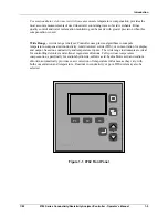
Page 15: ...rocess values show the instrument s tagname or other configurable text at the top of the screen Every display includes an alarm stripe a line dedicated to displaying process alarm messages status messages and system diagnostic messages whenever any are active One or more relays can also be used for alarm annunciation see 1 5 2 Dedicated function membrane keys to the right of the display on the fro...

Page 16: ...or retransmission of process variables or for Current Adjusting Type control using an output signal that is directly proportional to the input see 1 5 3 Relays Two 2A SPDT alarm control relays are standard with an additional two 3A relays either general purpose or hermetically sealed available as an option see Sub Section 2 17 These relays can be used to take advantage of special features such as ...

Page 17: ...ow 10 of the output scaling limit the output is scaled by a factor of 10 An internal relay can be dedicated to this function The relay closes contacts NC COM when the output is scaled to the low range and closes contacts NO COM when the range shift occurs The relay can be used to control an indicator or to switch the output to a second channel of a multipoint recorder when the range change occurs ...

Page 18: ...nsator selection for a reference conductivity represented by a single curve This method lacks the capability to accurately reflect the changing temperature coefficient of water for variations in temperature and conductivity on either side of that reference value Advanced high purity water temperature compensation determines the conductivity of an impurity at any concentration of water at any tempe...

Page 19: ... precise algorithms to compute temperature compensated conductivity total dissolved solids TDS or concentration for display and output based on conductivity and temperature inputs The wide range instruments are ideal for controlling deionizer and softener regenerant dilutions Full spectrum temperature compensation specifically for sodium hydroxide sulfuric acid hydrochloric acid and sodium chlorid...

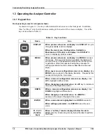
Page 20: ...feature is enabled the display will prompt for entry of the password before access to the menus is permitted Enter the password using the procedure for editing a parameter numeric value as described on the next page When any menu or configuration screen is on display Use MENU to go up a level in the display hierarchy Frequently this means returning to the main menu UP When a menu or configuration ...

Page 21: ...ressed use the DPP soft key to position the decimal point use the or soft keys to move the cursor to the digit to be changed use the UP and DOWN keys to increment or decrement the value when all digits necessary have been changed press ENTER Controlling an AutoClean operation manually To initiate an AutoClean operation manually press the DISPLAY key until the AutoClean screen is displayed Next pre...

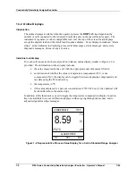
Page 22: ... connected to the Analyzer Controller an online display similar to Figure 1 2 is provided The information on this display includes the value measured by the cell with the appropriate unit of measure filled in an indication of whether the value is temperature compensated TC or not compensated NC the display can be toggled between displaying compensated and raw data using the F1 function key the tem...

Page 23: ...isplay also includes the temperature measured by each cell MIXED BEDS 1 AND 2 ALARM STRIPE NC CAL ACK C1 0 58 µS C2 0 25 µS TC Figure 1 3 Representative Combined Display Computed value If the Analyzer Controller is configured to calculate a computed value such as the ratio between the cells readings a screen will be available to display the value along with a label see Figure 1 4 CATION TRAIN A AL...

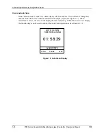
Page 24: ...ill be available If AutoClean is configured then the AutoClean screen will be included in the display cycle see Figure 1 5 When AutoClean is active the screen will display the time remaining When this screen is on display the function keys can be used to control the AutoClean operation as described in 1 3 1 AUTO CLEAN ALARM STRIPE START PAUSE STOP 01 58 29 TIME REMAINING Figure 1 5 AutoClean Displ...

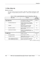
Page 25: ...MISSION configure parameters for using analog outputs for control and retransmission of process values 5 4 ALARMS specify value to be alarmed alarm setpoints deadbands and delay 5 6 DISCRETE CONTROL specify setpoints range limits etc to use relays for control 5 5 ADVANCED FEATURES set the clock set up automatic cell cleaning and specify the computed value to be displayed 5 7 5 8 5 9 CALIBRATION ca...

Page 26: ... listed below see below INSTRUMENT TAGGING configure tagname or other text to be displayed at the top of the screen 10 3 PRODUCT INFORMATION view software version and stored model number if a special technical support password is known alter model number in memory in case of hardware upgrades 10 4 SCREEN CONTRAST adjust display contrast 10 5 SECURITY assign password to limit access to configuratio...

Page 27: ...alyzer Controller and its features a little advance planning is recommended 1 5 2 Using Relays Relays assigned during I O setup Every 9782 model includes two internal relays Two more relays are available as an option During I O setup see 5 3 the 9782 s software will assign relays to the features you select The design of the Analyzer Controller allows multiple alarms to be assigned to one relay all...

Page 28: ... both Cell 1 and Cell 2 use AutoClean Relays 1 and 3 with no range status indication nor any discrete control For both Cell 1 and Cell 2 use range status indication Relays 2 and 4 with no AutoClean nor any discrete control When reading the tables keep in mind the following The entry Diagnostic in the tables indicates that the relay can be used to indicate the unit s failure of a self test see 9 4 ...

Page 29: ...us Alarm 3 Alarm 4 Alarm 1 and 2 and 3 and 4 Cell 1 Range Status Alarm 1 and 2 and 3 and 4 Cell 2 Range Status Alarm 1 and 2 and 3 and 4 and Diagnostic Cell 1 Range Status Alarm 1 and 2 and 3 and 4 and Diagnostic Cell 2 Range Status Range Status Alarm 1 or discrete control Cell 1 Range Status Alarm 3 or discrete control Alarm 4 or discrete control Discrete Control Alarm 1 and Alarm 2 Cell 1 Range ...

Page 30: ...ts are available as options These current or voltage outputs can be used to retransmit a process variable using an output signal that has been scaled An analog output that is directly proportional to an input can be used for Current Adjusting Type CAT control Despite the name of this control type voltage outputs can also be used When an output is used to retransmit a process variable the values re...

Page 31: ...environmental and electrical specs when selecting a site to install the Analyzer Controller 2 2 Unpack inspect and mount the unit 3 3 Check tag to confirm that unit is compatible with the voltage at your site 4 4 Install power wiring 4 5 Perform I O setup and configure the software to implement your control strategy 5 6 Wire inputs and outputs to match I O setup in Step 5 6 7 If AutoClean will be ...

Page 32: ...nformation about diagnostics status messages and system error messages Section 9 instructions for returning all parameter values to the factory settings Section 10 instructions for calibrating the outputs and changing the fuse Section 10 parts list Section 11 supplementary information for special applications and proportional control tuning tips appendices ...

Page 33: ...configuration alarm conditions and diagnostics Alarm messages status messages and diagnostic messages are available on all displays Keypad Monoplanar front panel with 8 keys Push button entry with tactile feedback 2 1 2 Physical Case Gray Noryl plastic NEMA 4X IP55 Rainproof and Outdoor Interior conductive coating to provide effective RFI EMI shielding Case Dimensions 156 x 156 x 178 mm 6 1 8 x 6 ...

Page 34: ...he year 2000 2 1 4 Electrical Power Requirements 120 10 Vac 47 63 Hz 15 VA 240 10 Vac 47 63 Hz 15 VA Memory retained by EEPROM when power is off Fuse Rating 120V operation 0 25 amp 250V 240V operation 0 125 amp 250V 2 1 5 Model Ranges Standard range models Standard Display Ranges 9782C S0 Conductivity microsiemens cm TDS Resistivity ohms cm Cell Constant Required cm 1 0 1 999 0 19 99 0 199 9 0 1 9...

Page 35: ... on temperature Maximum for sodium hydroxide allowed by the 9782 Analyzer is 10 at 0º C 13 at 25º C and 20 at 75º C with linear interpolation between these points The maximum concentration for hydrochloric acid is 15 5 above 40º C Measurements in the lower half of the concentration ranges and below 50º C may also use the next lower available cell constant 2 1 6 Operating Conditions Operating Condi...

Page 36: ...0 6 amps at 110 Vdc 2 amps at 30 Vdc Maximum switching power for ac 125 VA resistive for dc 60W resistive Optional alarm control relays 9782C _ _ R2 Two additional SPDT Form C rated at 3 amps at 120 Vac or 28 Vdc no analog outputs 9782C _ _ R0 Two hermetically sealed Form C rated at 3amps at 120 Vac or 28 Vdc plus one analog output 0 to 1 Vdc or 0 to 10 Vdc or isolated 4 to 20 mA Optional analog o...

Page 37: ...hms are for NaCl HCl NaOH or H2SO4 Displayed process value can be toggled between compensated and uncompensated while the Analyzer Controller is online 2 1 9 AutoClean Cell rinse schedule settings Timer Cycle Adjsutable up to 28 days with day hour minute resolution Rinse Time 1 1999 seconds Resume Process Time Delay 1 1999 seconds 2 1 10 Control Settings On off period 1 to 1000 seconds On off perc...

Page 38: ...ns Available Computed Values Description Equation Range ratio between the values measured by the cells Cell Cell 1 2 0 001 to 19 990 difference between the values measured by the cells Cell Cell 1 2 19 990 to 19 990 percent passage Cell Cell x 1 2 100 0 to 100 percent rejection x 1 1 2 100 Cell Cell 0 to 100 parts per million carbon dioxide 9782C S0 only 0 to 19 99 ppm ...

Page 39: ...Compliant Standard All Conductivity models are 2 cell inputs Standard Built in software for ON OFF Duration Adjusting and Pulse Frequency Type Discrete Control with Standard and or Optional relays Menu Driven Prompts for Display Programming Maintenance Text messages for Alarms Diagnostics Standard FM Haz Loc Approval Class I DIV 2 relays rated for 120 volt max Optional Built in software for propor...

Page 40: ... 1990 0M TABLE II AVAILABLE OUTPUTS No Outputs or Additional Relays 00 0 1V 0 10 V and 4 20 mA VC Two 4 20 mA C2 Three 4 20 mA C3 Two Additional Relays Hermetically Sealed R0 and 0 1V 0 10V 4 20 mA output 9782 _ Availability TABLE III OPTIONS Selection P C S User s Manual English E _ _ _ _ _ Pipe Mounting Kit None _ 0 _ _ _ _ Pipe Mounting Kit _ 1 _ _ _ _ Tagging None _ _ 0 _ _ _ Linen Note 1 _ _ ...

Page 41: ... 0 1999 ppb 0 01 0 19 99 0 19 990 ppb 0 1 0 199 9 0 199 9 ppm 1 0 0 1999 0 1999 ppm 10 0 19 990 0 10 000 ppm 25 or 50 Resistivity Cell Constant 0 19 99M 0 01 0 1 999M 0 1 0 199 9k 1 0 0 19 99k 10 0 1 999k 25 or 50 Note 4 Wide range should be selected if measuring the following conductivity TDS or weight concentration ranges WIDE RANGE Conductivity TDS Cell Constant 100 1999 0 1999 ppm 0 1 1000 19 ...

Page 42: ...Conductivity Resistivity Analyzer Controller 9782 Series Conductivity Resistivity Analyzer Controller Operator s Manual 7 99 2 10 ...

Page 43: ...iew Introduction This section contains instructions for unpacking preparing and mounting the Analyzer Controller Instructions for wiring are provided in Sections 4 and 6 Software configuration is described in Section 5 What s in this section The topics in this section are listed below Topic See Page 3 1 Overview 3 1 3 2 Unpacking and Preparing 3 2 3 3 Mounting 3 3 ...

Page 44: ...Honeywell immediately if there is equipment damage or shortage Do not return goods without contacting Honeywell in advance 3 Remove any shipping ties or packing material Follow the instructions on any attached tags and then remove such tags 4 All 9782 Analyzer Controllers are calibrated and tested at the factory prior to shipment Examine the model number on the nameplate Figure 3 1 to verify that ...

Page 45: ...the edges of the cutout between the case flange and the supplied U bracket which is fastened to the rear of the case The panel may be up to 3 8 in thick Cutouts for adjacent 9782 Analyzer Controllers may be no closer than 687 in horizontally and 937 in vertically resulting in a nominal edge to edge bezel separation of 078 in Note that if the panel already has a cutout for a 7082 instrument the sam...

Page 46: ...rs Horizontal Rear Pipe Mounting 6 12 030 155 57 0 76 1 37 34 92 2 75 69 85 C L 2 41 61 21 4 81 122 17 C L 6 00 152 40 2 20 Tapped Holes in rear of case for mounting bracket Dia holes 4 for lead wires accomodates conduit by customer 87 22 22 50 12 70 Square Terminal Boards Case Outline 7 00 040 177 80 1 02 2 76 70 05 min space between horizontal cutouts 687 17 45 5 516 140 11 047 0 1 19 0 5 516 14...

Page 47: ...195 07 1 52 3 06 77 80 7 43 070 188 72 1 78 1 00 25 40 IPS Pipe by customer Vertical Rear Pipe Mounting 1 50 38 10 3 00 76 20 C L 7 43 070 188 72 1 78 Top View Four holes in bracket or 1 4 dia mounting bolts bolts by customer 6 43 0 70 163 32 1 78 C L 1 06 025 26 92 0 64 6 27 040 159 26 1 02 25 max 6 35 R H Side View Wall Mounting Panel Mounting Panel Mounting into existing 7075 7076 7077 and 7078...

Page 48: ...92 2 75 69 85 C L 2 41 61 21 4 81 122 17 C L 6 00 152 40 2 20 Tapped Holes in rear of case for mounting bracket Dia holes 4 for lead wires accomodates conduit by customer 87 22 22 50 12 70 Square Terminal Boards Case Outline 7 21 040 183 13 1 02 2 76 70 05 min space between horizontal cutouts 687 17 45 5 516 140 11 047 0 1 19 0 5 516 140 11 047 0 1 19 0 2 76 70 05 125 3 18 R max permissible 937 23...

Page 49: ...5 07 1 52 3 06 77 80 7 64 070 194 06 1 78 Vertical Rear Pipe Mounting 1 50 38 10 3 00 76 20 C L 7 64 070 194 06 1 78 Top View Four holes in bracket or 1 4 dia mounting bolts bolts by customer 6 43 0 70 163 32 1 78 C L 1 27 025 32 26 0 64 6 27 040 159 26 1 02 25 max 6 35 R H Side View Wall Mounting Panel Mounting Customer Panel Panel Mounting into existing 7075 7076 7077 and 7078 series cutouts 1 0...

Page 50: ...Conductivity Resistivity Analyzer Controller 9782 Series Conductivity Resistivity Analyzer Controller Operator s Manual 7 99 3 8 ...

Page 51: ...he software and performing I O setup as described in Section 5 We recommend that you wait to install input and output wiring see Section 6 until after I O setup During I O setup the software will determine for you which relay to use for each feature What s in this section The topics in this section are listed below Topic See Page 4 1 Overview 4 1 4 2 General Wiring Practices for Power Wiring 4 2 4...

Page 52: ...rk stations and wrist straps must be used If soldering irons are used they must also be grounded A grounded work station is any conductive or metallic surface connected to an earth ground such as a water pipe with a 1 2 to 1 megohm resistor in series with the ground connection The purpose of the resistor is to current limit an electrostatic discharge and to prevent any shock hazard to the operator...

Page 53: ...nded wire size Observe all national and local electrical codes when making power connections Unless locally applicable codes dictate otherwise use 14 gauge 2 081 mm2 wire for ac power Power supply voltage and frequency within specs The power supply voltage and frequency must be within the limits stated in the specifications in Section 2 ...

Page 54: ...d to the Analyzer Controller If a 230 240 Vac line is to be connected use a 0 125 amp fuse If a 110 120 Vac line is to be connected use a 0 25 amp fuse 5 To ensure that the unit meets the requirements of EMC directive 89 336 EEC install the power line filter kit supplied with the Analyzer Controller Wind three turns of each wire 14 AWG maximum through the filter core for the two power and protecti...

Page 55: ...Power Wiring 7 99 9782 Series Conductivity Resistivity Analyzer Controller Operator s Manual 4 5 Power Terminations PE PE Protective Earth Ground L1 L2 N Figure 4 1 AC Power Terminals ...

Page 56: ...Conductivity Resistivity Analyzer Controller 9782 Series Conductivity Resistivity Analyzer Controller Operator s Manual 7 99 4 6 ...

Page 57: ...troller Every time the Analyzer Controller is powered up the unit performs a warm reset During a warm reset alarms are not cleared and outputs are maintained at their last value prior to the loss of power or initiation of the warm reset A warm reset has no effect on configuration or calibration values In addition to this warm reset a cold reset function is available to return ALL configuration val...

Page 58: ...ration The choices made during I O setup determine which prompts and menu choices are available during configuration Even though I O setup is performed first I O SETUP is last on the main menu because you usually only have to access this function a few times in the life of your Analyzer Controller Purpose of configuration menu items The configuration menu contains the following items for accessing...

Page 59: ...d in 5 3 If a computed value is used it is significant which cell is considered Cell 1 and which is Cell 2 This must be taken into account when wiring the inputs See 6 3 for details Illustrations The procedures in this section contains illustrations of display screens These pictures are intended to show the types of information displayed on each screen However the screens you will actually see on ...

Page 60: ...e display range When set to HIGH the decimal point will automatically be shifted one place to the left to provide greater resolution when the displayed value falls below 10 of the high display range and conversely be shifted back when the value increases above 10 This selection of low or high display range has no effect on the fixed or auto output range status For conductivity measurement the unit...

Page 61: ...port The model number of the unit was stored in the 9782 memory at the factory Each combination of features has a unique model number see Section 2 Therefore the processor can use this information to determine which prompts and selections are appropriate Entering the new number when you modify the hardware will let the processor know about the new hardware capabilities As a result you will be able...

Page 62: ...to the next screen 4 ATTENTION RECONFIG OF ANY I O SETUP PARM WILL RESET CONFIG PARMS TO FACTORY DEFAULTS MENU TO EXIT DIAGNOSTICS PREV NEXT I O setup is normally performed only once before field connections are made to the Analyzer Controller You can also use this menu to view parameters If you do not change anything you will not cause a cold reset of the unit You can exit now using the MENU key ...

Page 63: ...other functions However by selecting AA all alarms can be directed to a single relay 9 RELAY ACTIVATION STATE ON ALARM SELECT DE ENERGIZE DIAGNOSTICS PREV NEXT The display will indicate whether relay activation in case of alarm or control output ON state is currently ENERGIZE or DE ENERGIZE Use this display to specify the desired relay action 10 MEASUREMENT TYPE SELECT COND TDS DIAGNOSTICS PREV NE...

Page 64: ...on the label on the potted connector housing of the cell The cell constant is indicated by the three characters following the four digit series number For example a cell labeled 4973 001 has a 0 01 cell constant When in doubt refer to the manual supplied with the cell 2 Changing the cell constant causes the unit to perform a cold reset returning all configuration and calibration trim or TDS factor...

Page 65: ...rocess values can be scaled A retransmitted computed value always uses Fixed Linear Range 16 I O SETUP COMPLETE PRESS ENTER TO CONTINUE DIAGNOSTICS PREV At this point you have completed the I O setup menu If you have changed at least one parameter other than solution temperature compensation the unit will perform a cold reset see page 5 1 UPDATING EEPROM DIAGNOSTICS UPDATING EEPROM PRESS ENTER TO ...

Page 66: ...ocess variables is shown in Table 5 2 Table 5 2 Procedure for Configuring CAT Control and or Retransmission of Process Variables Step Screen Action 1 MENU CONFIGURATION CALIBRATION MAINTENANCE I O SETUP DIAGNOSTICS PREV NEXT Go to CONFIGURATION CAT RETRANSMISSION CONFIGURATION CAT RETRANSMISSION ALARMS DISCRETE CONTROL ADVANCED FEATURES DIAGNOSTICS PREV NEXT ATTENTION Any value entered for one of ...

Page 67: ...al band parameters to define the output span 5 RETRANSMISSION OUTPUT 1 OUTPUT 2 DIAGNOSTICS PREV NEXT To configure retransmission on a unit with a single analog output go to CONFIGURATION CAT RETRANSMISSION RETRANSMISSION To configure retransmission on a unit with three analog outputs go to CONFIGURATION CAT RETRANSMISSION and select the output to be configured 6 OUTPUT 1 SCALING LINFIXEDRNG INPUT...

Page 68: ...implemented based on any measured or computed value DAT and PFT control can be based on Cell 1 input Cell 2 input the computed ratio Cell Cell 1 2 or the computed difference Cell Cell 1 2 If you specified one or more of these discrete control types during I O setup you will be able to configure the related parameter values For a discussion of tuning proportional control applicable to PFT and DAT c...

Page 69: ...his screen to specify the length of the cycle period for all timers To configure an individual timer associated with one of the relays select it from the menu 3 CYCLE TIMER 1 RLY2 INPUT C1 ACTION HIGH SETPOINT 15000 µS DEADBAND 250 µS ONTIME 50 DIAGNOSTICS The relay assigned to this On Off control output during I O setup will already be filled in This is read only information Specify the process v...

Page 70: ...ICS 2 PFT CONTROL DB FREQ RATE 100 P M PFT1 PFT2 DIAGNOSTICS Specify the maximum frequency rate in pulses per minute representing 100 output Be sure this rate is compatible with the controlled device This rate will be used for all PFT outputs in the Analyzer Controller Use this screen to select the PFT control output to be configured 3 PFT 1 OUTPUT RLY2 INPUT C1 SETPOINT 15000 µS PB LIMIT 250 µS D...

Page 71: ... soon as it is entered DISCRETE CONTROL ON OFF PFT DAT DIAGNOSTICS 2 DAT CONTROL CYCLE PERIOD 200 S DAT1 DAT2 DIAGNOSTICS Specify the length of the cycle period in seconds for the time proportioned control Use this screen to select the DAT control output to be configured 3 ON OFF CYCLE TIMER 1 OUTPUT RLY2 INPUT C1 SETPOINT 15000 µS PB LIMIT 250 µS DIAGNOSTICS The relay assigned to this DAT control...

Page 72: ...D FEATURES DIAGNOSTICS PREV NEXT ATTENTION Any value entered for one of these alarm related parameters will take effect as soon as it is entered 2 ALARMS DELAY TIME 3 S ALARM1 ALARM2 ALARM3 ALARM4 DIAGNOSTICS Use this screen to enter a delay time to prevent brief process upsets from activating an alarm The delay entered here will apply to all alarms Select the alarm to be configured 3 ALARM1 OUTPU...

Page 73: ...TUP CONFIGURATION CAT RETRANSMISSION ALARMS DISCRETE CONTROL ADVANCED FEATURES DIAGNOSTICS PREV NEXT ADVANCED FEATURES CLOCK SETUP COMPUTED VALUE AUTO CLEAN DIAGNOSTICS 2 24 HOUR CLOCK SETUP CLOCK OFF HOURS 13 MINUTES 30 DIAGNOSTICS NEXT Set the clock For example if you will start the clock at 1 30 PM enter 13 hours 30 minutes Start the clock and specify what should happen to the clock if the powe...

Page 74: ...ning To temporarily disable timer initiated AutoClean you must either turn off the 24 hour clock which preserves your timer setup or set the timer to all zeros see Step 3 in Table 5 8 Unless the Time Remaining display is on screen you will not see the AUTO CLEAN message during a scheduled cleaning Operator initiated operation To operate in this mode you must have the AutoClean Time Remaining displ...

Page 75: ...cedure If AutoClean was selected during I O setup follow the procedure in Table 5 8 to use the displayed screens for configuration when AUTO CLEAN is selected from the ADVANCED FEATURES configuration menu Table 5 8 Procedure for Configuring AutoClean Step Screen Action 1 MENU CONFIGURATION CALIBRATION MAINTENANCE I O SETUP DIAGNOSTICS PREV NEXT Go to CONFIGURATION ADVANCED FEATURES AUTO CLEAN CONF...

Page 76: ...tes the rinse should occur In our example the rinse will occur every third day at 4 30 PM If you plan to use AutoClean but initiate rinses manually using the real time AutoClean Time Remaining display a specify the number of days as zero b specify the number of hours and minutes in the interval between rinses as zero also IF YOU ENTER ALL ZEROS NO AUTOMATIC RINSES WILL BE PERFORMED Specify where t...

Page 77: ...er million carbon dioxide standard range analyzers only Appendix B includes examples of applications using these values ATTENTION If a computed value is used it is significant which cell is considered Cell 1 and which is Cell 2 This must be taken into account when wiring the inputs See 6 3 for details Procedure Use the procedure in Table 5 9 to specify a computed value Table 5 9 Procedure for Spec...

Page 78: ...istivity Analyzer Controller 9782 Series Conductivity Resistivity Analyzer Controller Operator s Manual 7 99 5 22 Step Screen Action 2 COMPUTED VALUE SELECT DIFFERENCE DIAGNOSTICS NEXT Specify the value to be computed ...

Page 79: ...bed in Section 8 Not every choice shown in this table applies to every application Table 5 10 Menu Choices and System Defaults PARAMETER CHOICES or RANGE Default is underlined I O setup measurement type 9782C S0 COND TDS total dissolved solids RESISTIVITY 9782C W0 COND TDS CONCENTRATION I O setup solution temperature compensation type 9782C S0 NaCl NH3 ACID ETA MORPHOLINE NaCl TDS NH3 TDS MORPHOLI...

Page 80: ...elay 1 ALM2 alarm 2 default for Relay 2 ALM3 alarm 3 default for Relay 3 ALM4 alarm 4 default for Relay 4 A1 D alarm 1 or diagnostic A2 D alarm 2 or diagnostic A3 D alarm 3 or diagnostic A4 D alarm 4 or diagnostic A1 2 alarm 1 or 2 A3 4 alarm 3 or 4 12 D alarm 1 or 2 or diagnostic AA D any alarm or diagnostic 234D alarm 2 or 3 or 4 or diagnostic RNGD range switch or diagnostic AA any alarm RNGS ra...

Page 81: ...ess variable or computed value to be used as basis for discrete control output configuration process variable or computed value alarmed C1 Cell 1 value C2 Cell 2 value TMP1 temperature value from Cell 1 TMP2 temperature value from Cell 2 T1 2 temperature 1 and or 2 only available for alarming RATO computed ratio Cell Cell 1 2 REJ computed percent rejection x 1 1 2 100 Cell Cell PSG computed percen...

Page 82: ... 100 REJECTION computed percent rejection x 1 1 2 100 Cell Cell PPMCO2 computed parts per million carbon dioxide 9782C S0 only maintenance display resolution LOW HIGH maintenance security enabled YES NO maintenance password 0000 to 9999 default 0000 maintenance lead resistance compensation wire gauge AWG wide range models only 12 14 16 18 maintenance lead resistance compensation length wide range ...

Page 83: ...asurement in pure water applications where plastic piping is used you may have to provide an earth ground for the cell If the cell constant is 0 01 0 1 or 1 0 run a wire from the screw terminal on the Analyzer Controller to which the black wire in the cell lead is attached to the lower card retainer bracket screw See Note 4 in Figure 6 1 Do not ground cells having cell constants of 10 25 or 50 Wha...

Page 84: ...assemblies containing static sensitive devices be carried in conductive plastic bags When adjusting or performing any work on such assemblies grounded work stations and wrist straps must be used If soldering irons are used they must also be grounded A grounded work station is any conductive or metallic surface connected to an earth ground such as a water pipe with a 1 2 to 1 megohm resistor in ser...

Page 85: ...26 mm2 or heavier signal input wiring is required Avoiding interference Instrument wiring is considered Level 1 per section 6 3 of IEEE STD 518 for plant facilities layout and instrumentation application Level 1 wiring must not be run close to higher level signals such as power lines or drive signals for phase fired SCR systems etc Unprotected input wiring in high electrical noise environments is ...

Page 86: ...ased on the process variable value measured by both cells Therefore it matters which cell is considered Cell 1 and which is Cell 2 The Analyzer Controller determines the cell s identity based upon which terminals receive the cell s input see Figure 6 1 If you have set up the 9782 s software to use a computed value be sure to wire the cell leads correctly The available computed values are RATIO rat...

Page 87: ...e power off remove the safety cover by removing the single screw holding it in place 5 Connect the inputs from the cells to the terminals in accordance with the system setup assignments Refer to the wiring diagram provided with the cells and to Figure 6 1 There are 2 resistors one for cell 2 input and one for cell 2 thermistor input which are installed in every unit at the factory These resistors ...

Page 88: ...nsator Cell 2 Electrodes Cell 1 Electrodes Note 4 Case as viewed from front Note 3 1 2 3 4 5 6 O U T 1 O U T 1 O U T 2 O U T 2 O U T 3 O U T 3 Output Board Connections 4 20 mA Two Cell Cat 9782 MultiOptions K black W white G green R red B blue N brown O orange Y yellow A gray V violet P pink S slate T tan Color Code a n23177 NOTES 1 Relay 1 2 contacts max ratings Resistive Load Current 2A AC or DC...

Page 89: ...ely during normal non alarm operation or when the control point is not active the NC contacts will be open and the NO contacts will be closed If de energize on alarm is selected a power loss will force all relays to the same position as an alarm condition The relay contact maximum ratings are in Table 6 3 Table 6 3 Relay Contact Maximum Ratings Current Standard 0 6 amps at 120 240 Vdc 0 6 amps at ...

Page 90: ...e required to remove power 3 With the power off open the case Grasp the bottom center portion of the front bezel and pull it downward and toward you slightly to disengage the bottom of the bezel from the edge of the case Lift the bezel gently to disengage it from the top edge of the case Swing the bezel to the left The bezel and display assembly is mounted on pivot arms The safety cover with its w...

Page 91: ...ard and toward you slightly to disengage the bottom of the bezel from the edge of the case Lift the bezel gently to disengage it from the top edge of the case Swing the bezel to the left The bezel and display assembly is mounted on pivot arms The safety cover with its warning label will be visible 3 With the power off remove the safety cover by removing the single screw holding it in place 4 Disco...

Page 92: ...ntacts NC COM when the output is scaled to the low range Range 1 in Figure 6 2 and closes contacts NO COM when scaled to the high range Range 2 in Figure 6 2 Interconnections The range change capability illustrated in Figure 6 2 is accomplished with interconnections shown in Figure 6 3 Similar range identification could be obtained using a 2 pen or event pen recorder Point 1 Terminals 1 low range ...

Page 93: ...ller Operator s Manual 6 11 9 8 7 6 5 4 3 2 1 m A 10 VC 1 9782 Conductivity Analyzer NO NC R R 1 3 5 2 4 6 1 3 5 2 4 6 Multi point Recorder Input Terminal Board a n23179 where R 250 ohms Figure 6 3 Interconnections between 9782 and Recorder with Range Identification by Point Change ...

Page 94: ...Conductivity Resistivity Analyzer Controller 9782 Series Conductivity Resistivity Analyzer Controller Operator s Manual 7 99 6 12 ...

Page 95: ... advantage of this feature you must Select it during I O setup see Section 5 Set the clock and specify the frequency and duration of the rinse see Section 5 Wire the relay assigned to this operation during I O setup to operate the necessary valves See Section 6 for relay wiring Install piping and valves as diagrammed in this section What s in this section The topics in this section are listed belo...

Page 96: ...re 7 1 to direct rinsing fluid to the cells for the configured rinse duration 1 to 1999 seconds If the measured sample is normally returned to the process but quantities of rinsing fluid cannot be tolerated there use an additional 3 way solenoid valve S4 It is activated simultaneously with S1 to divert the discharge to drain 3 At the end of the configured rinse time Relay 1 de activates solenoid v...

Page 97: ...ample cell to process to drain 9782 S4 S1 Items outside this area provided byuser a n23185 Figure 7 1 Automatic Cell Wash Setup Select valves and fittings with appropriate pressure ratings Make the process connections as shown in Figure 7 1 Be sure that valves and fittings S1 have sufficient pressure ratings to withstand pressure peaks which will occur when process flow is blocked Minimize liquid ...

Page 98: ...Conductivity Resistivity Analyzer Controller 9782 Series Conductivity Resistivity Analyzer Controller Operator s Manual 7 99 7 4 ...

Page 99: ... instrument is used to determine the conductivity of the process In this case the process fluid becomes the reference solution Calibration trim can be removed as described in 8 5 For accurate measurement of total dissolved solids TDS a conversion factor is entered for each cell as described in 8 6 ATTENTION Any time a cold reset is performed the calibration trim and TDS values will be removed The ...

Page 100: ...without TDS and Cell 2 with TDS then the calibration menu will be CELL CAL FACTOR CAL TRIM C1 TDS CVSN FACTOR C2 REMOVE CAL TRIM C1 REMOVE CAL TRIM C2 If both cells solution temperature compensation is set up with TDS then the calibration menu will be CELL CAL FACTOR TDS CVSN FACTOR C1 TDS CVSN FACTOR C2 REMOVE CAL TRIM C1 REMOVE CAL TRIM C2 Therefore the screens on your unit may not match exactly...

Page 101: ...fect of ambient conditions on process temperature measurement Rinse the cells thoroughly with de ionized water before immersing in a reference solution Always deactivate control or alarm circuits before removing cells from the process Do calibration trim with a reference solution which is at about the same temperature and conductivity as the process solution Inspect and if necessary clean the cell...

Page 102: ...nt cell Procedure To enter the cal factor for each cell follow the procedure in Table 8 1 Table 8 1 Procedure for Entering Cal Factor Step Screen Action 1 MENU CONFIGURATION CALIBRATION MAINTENANCE I O SETUP DIAGNOSTICS Go to CALIBRATION CELL CAL FACTOR The cell constant entered for each cell during I O setup will be displayed To enter the unique cal factor for each cell use the indicated function...

Page 103: ...case the process fluid becomes the reference solution Materials and procedure To perform calibration trim using a standard reference solution follow the instructions in Table 8 3 Materials required are A reference solution of known conductivity near the point of interest with the temperature controlled or measured and compensated to within 1 C Conductivities of potassium chloride solutions are pro...

Page 104: ... C1 147 00 µS DIAGNOSTICS The display will show the conductivity of the reference solution as measured by the cell and Analyzer Controller system Once the reading is stable change the value to match the actual conductivity of the reference solution at its current temperature Press ENTER to save the calibration trim value If the calibration trim adjustment is successful the calibration menu will ag...

Page 105: ...Values Step Screen Action 1 MENU CONFIGURATION CALIBRATION MAINTENANCE I O SETUP DIAGNOSTICS Go to CALIBRATION REMOVE CAL TRIM C1 CALIBRATION CELL CAL FACTOR CAL TRIM 1 CAL TRIM 2 REMOVE CAL TRIM C1 REMOVE CAL TRIM C2 DIAGNOSTICS 2 REMOVE CAL TRIM ATTENTION THIS FUNCTION WILL CANCEL ANY PREVIOUS CALIBRATIONS DIAGNOSTICS A calibration trim message will be displayed Go to the next screen 3 REMOVE CA...

Page 106: ...ed above to give an official TDS value Next divide the TDS value by the conductivity of the sample to yield the conversion factor for that particular process fluid The conversion factor is then entered into the 9782 to normalize the TDS readout With power plant cation conductivity measurements ion chromatography results may be used to establish the conversion factor for readout in ppb chloride or ...

Page 107: ...BRATION CELL CAL FACTOR TDS CVSN FACTOR C1 TDS CVSN FACTOR C2 REMOVE CAL TRIM C1 REMOVE CAL TRIM C2 DIAGNOSTICS If you plan to calibrate do it before entering the theoretically derived TDS conversion factor see previous page 2 TDS CONVRSN FACTOR C1 0 5 DIAGNOSTICS Enter the appropriate TDS conversion factor for the selected cell 3 TDS CONVRSN FACTOR ACCEPTED AND SAVED DIAGNOSTICS If the factor ent...

Page 108: ...Conductivity Resistivity Analyzer Controller 9782 Series Conductivity Resistivity Analyzer Controller Operator s Manual 7 99 8 10 ...

Page 109: ...or messages All these messages are displayed on the alarm stripe in reverse video with the background lit and the letters black If more than one message is active the display will cycle through all the messages then repeat What s in this section The topics in this section are listed below Topic See Page 9 1 Overview 9 1 9 2 System Status Messages 9 2 9 3 Process Alarm Messages 9 3 9 4 On Line Diag...

Page 110: ...is active All alarms and outputs are held for the duration of the AutoClean operation To see how much time is remaining until the next scheduled AutoClean operation use the DISPLAY key to access the special Time Remaining screen CAL ADJ FAILED This message indicates that a calibration operation has been unsuccessful RETRIEVING DATA This message is displayed during I O setup configuration and calib...

Page 111: ...red to alarm on the Cell 1 and or Cell 2 value exceeding high alarm or falling below low alarm the configured alarm setpoint DIFFERENCE HIGH ALM DIFFERENCE LOW ALM Indicates alarm state if the Analyzer Controller is PASSAGE HIGH ALM PASSAGE LOW ALM configured to alarm on a computed value exceeding high REJECT HIGH ALM REJECT LOW ALM alarm or falling below low alarm the configured alarm PPM CO2 HIG...

Page 112: ...will stop updating until the condition and alarm message clears Instead to indicate an invalid display the display will alternately flash 0 0 and either the last known value or the high end limit for the cell constant Check cell to make sure it is connected to terminals Make sure cell constant is correct for expected conductivity range CELL 1 TEMP ERROR or CELL 2 TEMP ERROR background Cell tempera...

Page 113: ...en Action 1 MENU CONFIGURATION CALIBRATION MAINTENANCE I O SETUP DIAGNOSTICS PREV NEXT Go to MAINTENANCE OFF LINE FUNCTIONS DISPLAY TEST MAINTENANCE OFFLINE FUNCTIONS INSTRUMENT SETUP LEAD RESISTANCE COMP DIAGNOSTICS PREV NEXT OFF LINE FUNCTIONS DISPLAY TEST KEYBOARD TEST OUTPUT RELAY TEST OUTPUT CALIBRATON DIAGNOSTICS PREV NEXT 2 DISPLAY TEST DIAGNOSTICS DTEST Pressing the specified function key ...

Page 114: ... 7 99 9 6 Step Screen Action 3 OFF LINE FUNCTIONS DISPLAY TEST KEYBOARD TEST OUTPUT RELAY TEST OUTPUT CALIBRATON DIAGNOSTICS PREV NEXT Go to MAINTENANCE OFF LINE FUNCTIONS KEYBOARD TEST 4 KEYBOARD TEST PRESS A KEY TO TEST MENU TO EXIT DIAGNOSTICS Press any key except MENU to display the name of the key Use MENU to exit ...

Page 115: ...off the power to the Analyzer Controller More than one switch may be required to remove the power 2 With the power off open the case Grasp the bottom center portion of the front bezel and pull it downward and toward you slightly to disengage the bottom of the bezel from the edge of the case Lift the bezel gently to disengage it from the top edge of the case Swing the bezel to the left The bezel an...

Page 116: ... analog output values match those selected Also listen for the click of an energized relay If the results of the analog output test are not satisfactory recalibrate the output s zero and span using the procedure in 10 2 If the results of the relay output test are not satisfactory consult Honeywell for assistance 9 OUTPUT TEST 01 02 03 R1R2R3R4 100 75 50 A A A N 0 100 75 A N A A 0 0 100 A A N A 0 0...

Page 117: ...or Other Display String 10 6 10 4 Viewing Product Information and Changing Model Number Stored in Memory 10 7 10 5 Adjusting the Screen Contrast 10 9 10 6 Entering a Password for Security 10 10 10 7 Resetting All Configuration and Calibration Values to Factory Settings 10 11 10 8 Entering Values for Lead Resistance Compensation 10 12 10 9 Replacing the Fuse 10 14 WARNING While the unit is powered ...

Page 118: ... device to fail completely but may cause early failure Therefore it is imperative that assemblies containing static sensitive devices be carried in non conductive plastic bags When adjusting or performing any work on such assemblies grounded work stations and wrist straps must be used If soldering irons are used they must also be grounded A grounded work station is any conductive or metallic surfa...

Page 119: ...r capable of resolving 0 01 mA over the range 0 to 20 mA dc voltage outputs a 250 ohm 0 05 shunt and a volt meter capable of measuring 1 to 5 Vdc within 1 mV A screwdriver to fit the terminal block screws is also required Procedure To calibrate outputs follow the procedure described in Table 10 1 The output terminals are inside the case as shown in Figure 6 1 WARNING While the unit is powered a po...

Page 120: ...splay assembly is mounted on pivot arms The safety cover with its warning label will be visible 3 With the power off remove the safety shield by removing the single screw holding it in place 4 Label and remove the field wiring connected to the analog output terminals 5 Feed the test wiring through conduit hole in the case and connect the appropriate type of meter to the terminals for the output to...

Page 121: ...GNOSTICS Use the UP and DOWN keys to correct the reading on the test meter To save the correction press ENTER 10 OUTPUT CALIBRATION SAVED MENU TO EXIT DIAGNOSTICS This screen confirms that the value was saved 11 To calibrate additional values repeat Steps 1 through 10 including powering down the unit before changing the connections to the output terminals 12 When output calibration has been comple...

Page 122: ...ges are active Table 10 2 Procedure for Specifying a Tagname or Other Display String Step Screen Action 1 MENU CONFIGURATION CALIBRATION MAINTENANCE I O SETUP DIAGNOSTICS PREV NEXT Go to MAINTENANCE INSTRUMENT SETUP INSTRUMENT TAGGING MAINTENANCE OFFLINE FUNCTIONS INSTRUMENT SETUP LEAD RESISTANCE COMP DIAGNOSTICS PREV NEXT INSTRUMENT SETUP INSTRUMENT TAGGING PRODUCT INFO SCREEN CONTRAST SECURITY R...

Page 123: ...the stored model number If the password was not supplied with the new option card call the Honeywell Technical Assistance Center Before calling for technical support follow the procedure in Table 10 4 to determine the version of the software in the Analyzer Controller The support team will ask for this information Procedure Use the procedure in Table 10 4 to see the software version and model numb...

Page 124: ...r it when prompted This password is included with the instructions for installing the new card 1 4 MODEL NUMBER 9782X nn Xn XXXX DIAGNOSTICS ATTENTION Changing the model number stored in memory will do a cold reset of the unit returning ALL configuration values to the factory settings shown in Table 5 1 During a cold reset some I O setup values will also be returned to the defaults and the cal fac...

Page 125: ...IGURATION CALIBRATION MAINTENANCE I O SETUP DIAGNOSTICS PREV NEXT Go to MAINTENANCE INSTRUMENT SETUP SCREEN CONTRAST MAINTENANCE OFFLINE FUNCTIONS INSTRUMENT SETUP LEAD RESISTANCE COMP DIAGNOSTICS PREV NEXT INSTRUMENT SETUP INSTURMENT TAGGING PRODUCT INFO SCREEN CONTRAST SECURITY RESET UNIT DIAGNOSTICS 2 SCREEN CONTRAST 20 USE UP DOWN ARROW KEYS TO ADJUST ENTER TO SAVE DIAGNOSTICS Use the UP and D...

Page 126: ... needed to edit the model number stored in memory as described in 10 5 Procedure Follow the procedure in Table 10 5 to enter a password Table 10 5 Procedure for Entering a Password Step Screen Action 1 MENU CONFIGURATION CALIBRATION MAINTENANCE I O SETUP DIAGNOSTICS PREV NEXT Go to MAINTENANCE INSTRUMENT SETUP SECURITY MAINTENANCE OFFLINE FUNCTIONS INSTRUMENT SETUP LEAD RESISTANCE COMP DIAGNOSTICS...

Page 127: ...power or initiation of the cold reset A warm reset has no effect on configuration or calibration values Procedure To do a cold reset returning all configuration and calibration values to their factory settings follow the procedure in Table 10 6 Table 10 6 Procedure for Resetting All Configuration to Factory Settings Step Screen Action 1 MENU CONFIGURATION CALIBRATION MAINTENANCE I O SETUP DIAGNOST...

Page 128: ...e and length The resistance of each available gauge choice in copper wire is 12 AWG 1 6 ohms per 1000 feet 14 AWG 2 5 ohms per 1000 feet 16 AWG 4 0 ohms per 1000 feet 18 AWG 6 4 ohms per 1000 feet For example suppose each lead between the cell and Analyzer Controller consists of 500 feet of 12 gauge wire and 1000 feet of 18 gauge wire 1000 ft of 18 AWG 500 ft of 12 AWG 9782 Honeywell Junction Cond...

Page 129: ...N CALIBRATION MAINTENANCE I O SETUP DIAGNOSTICS PREV NEXT Go to MAINTENANCE LEAD RESISTANCE COMP MAINTENANCE OFFLINE FUNCTIONS INSTRUMENT SETUP LEAD RESISTANCE COMP DIAGNOSTICS PREV NEXT 2 LEAD RESISTANCE COMP WIRE GAUGE 12AWG WIRE LENGTH CELL1 100FT CELL2 150FT DIAGNOSTICS PREV NEXT Use this screen to specify the gauge used for leads to both cells and the length of one lead to each cell If mixed ...

Page 130: ...ntaining fuses 9 8 7 6 5 4 3 Figure 10 2 Location of Power Fuse WARNING Disconnect power before opening the instrument case to replace the fuse A potentially lethal shock hazard exists inside the case if the unit is opened while powered More than one switch may be required to disconnect power ATTENTION To avoid potentially serious damage to expensive components a blown fuse should not be replaced ...

Page 131: ...from the edge of the case Lift the bezel gently to disengage it from the top edge of the case Swing the bezel to the left The bezel and display assembly is mounted on pivot arms The safety cover with its warning label will be visible 5 With the power off remove the safety cover by removing the single screw holding it in place 6 If more room is needed remove the circuit card retainer bracket at the...

Page 132: ...Conductivity Resistivity Analyzer Controller 9782 Series Conductivity Resistivity Analyzer Controller Operator s Manual 7 99 10 16 ...

Page 133: ...r Operator s Manual 11 1 11 Accessories and Replacement Parts List 11 1 Overview Introduction This section provides part numbers for field replaceable parts and for accessories What s in this section The topics in this section are listed below Topic See Page 11 1 Overview 11 1 11 2 Part Numbers 11 2 ...

Page 134: ...ts installation instructions 1 51198066 501 For replacement of existing card card 1 2 current outputs on pH cond analyzer installation instructions 1 51198067 501 For replacement of existing card card 1 3 current outputs on pH cond analyzer installation instructions 1 51198176 501 Non Backlit LCD Display display 1 installation instructions 1 51198176 502 Backlit LCD Display w solid state LED displ...

Page 135: ...tallation instructions 1 51198174 501 Bezel ass y for Non Backlit Display Units assembly 1 Wide Standard Range Conductivity installation instructions 1 51205779 501 Bezel ass y for Backlit Display Units assembly 1 Wide Standard Range Conductivity installation instructions 1 AVAILABLE CABLES Part Number Description Parts Included Note Extension lead wires up to 500 ft standard range models 834059 3...

Page 136: ...Conductivity Resistivity Analyzer Controller 9782 Series Conductivity Resistivity Analyzer Controller Operator s Manual 7 99 11 4 ...

Page 137: ...h Treatment takes too long but no unacceptable overshoot After observing treatment performance some improvement may be possible If treatment takes too long and there has been no unacceptable overshoot beyond the setpoint make one or more the following changes Increase the reagent delivery capacity Increase the reagent concentration Decrease the proportional band width by adjusting the proportional...

Page 138: ...Conductivity Resistivity Analyzer Controller Appendix A 2 9782 Series Conductivity Resistivity Analyzer Controller Operator s Manual 7 99 ...

Page 139: ...ages it can identify exhaustion before breakthrough Cell 2 Cell 2 Cell 1 Cell 2 Cell 1 Inlet Cell 1 Mixed Bed D I Water Cation Bed Anion Bed a n 23188 Reverse Osmosis Reverse Osmosis efficiency is monitored by comparing inlet and outlet conductivity or TDS Automatic calculations of Percent Rejection or Percent Passage are provided If readout is in resistivity cell locations are interchanged Temper...

Page 140: ...wo different alarms and are used A difference kind of diagnostic can be provided by a precision check resistor in place of one cell to give continuous Analyzer Controller checking at one value See also Appendix D 9782 Analyzer OutputSignal Difference Alarm Cell1 Cell2 Process a n23190 Parts Rinsing Parts rinsing is usually controlled by conductivity to obtain adequate rinsing without wasting exces...

Page 141: ...io Cell Cell 1 2 Typical Ratio Range is 1 to 1 25 Steam Power Measurements The three conductivity measurements in power plants relate to water chemistry parameters as follows Specific conductivity chemical treatment level Cation conductivity total anion contaminants Degassed conductivity non volatile anion contaminants Cation minus degassed conductivities carbon dioxide The 9782 Standard Range Ana...

Page 142: ...e of sodium hydroxide by conductivity is limited by temperature The conductivity is limited by temperature The conductivity of sodium hydroxide reaches a maximum value near 14 at 0º C and 29 at 100º C Near the maximum there is poor resolution and no reliable way to know which side of the peak is being measured Therefore the 7082 measurement range is restricted by temperature to assure reliable val...

Page 143: ...echnical Assistance Center Location of switches Two 8 position DIP switches are mounted on the microprocessor board far left board The switch locations are shown in Figure C 1 9 8 7 6 5 4 3 2 1 1 2 3 4 5 6 Switch1 Switch2 Figure C 1 Microprocessor Board DIP Switches Note that S1 switch 030480 CR1 CR8 and CR12 CR16 188056 are not used as of June 1993 SW1 all positions set to off Regardless of the o...

Page 144: ...icroprocessor Board Switch Settings Option SW2 1 SW2 2 SW2 3 SW2 4 SW2 5 SW2 6 SW2 7 SW2 8 None OFF OFF OFF OFF OFF OFF OFF OFF Single Parameter Current or Voltage Output OFF OFF OFF OFF OFF OFF OFF OFF Auxiliary Relays OFF OFF ON OFF OFF OFF OFF OFF Two Analog Outputs ON OFF OFF OFF OFF OFF OFF OFF Three Analog Outputs ON ON OFF OFF OFF OFF OFF OFF ...

Page 145: ...the conductivity cell to the Cell 1 input terminals instead of a Cell 2 input install a check resistor at the Cell 2 input terminals The Cell 2 process value should always be the appropriate value for the resistor see equations below Configure an alarm to monitor this value Set cal factor and calibration trim for ideal conditions When a check resistor is used instead of cell input the Analyzer Con...

Page 146: ... of 10 M ohms use cell constant 0 01 and perform the following calculation 100 K ohms 0 01 x 10 000 000 Concentration values If a wide range model is used for concentration measurement obtain the appropriate check resistance value from the table below Data for Concentration Range Measurements Material Weight Concentration Simulation Resistance ohms 25º C Cell Constant 10 25 50 Hydrochloric Acid HC...

Page 147: ......

Page 148: ...Industrial Automation and Control Honeywell Inc 1100 Virginia Drive Fort Washington Pennsylvania 19034 ...

Reviews: