


2-10
MAN0448_Issue 13_01-2010
5704 Control System
005704-M-5001 A03249
CHAPTER 2 - SySTEM DESCRIPTION
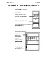
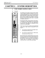
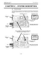
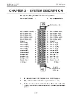
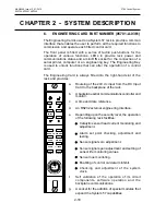
4.4 Physical layout
The physical layout of the Four Channel Control Card is shown below.
Analogue Output Modules, when fitted, plug into channel sockets as
shown:
Plug-in Sockets for Analogue Output Modules
(From left to right - Channel 1 2 3 4)
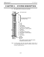
liquid Crystal
Display
lEDs
Reset/Select
Push Button
Switch
32-Way Connector (SK2)
To Backplane
26-Way D Type Connector (SK1)
To Quad Relay Interface Cards
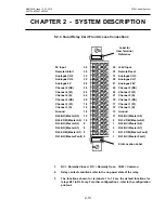
liquid Crystal
Display
lEDs
Reset/Select
Push Button
Switch
32-Way Connector (SK2)
To Backplane
26-Way D Type Connector (SK1)
To Quad Relay Interface Cards
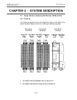
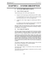
4 CHANNEl
CONTROl CARD
05704-A-0144 Iss.
CATAlyTIC INPUT
Ser/Batch No.
4 CHANNEl
CONTROl CARD
05704-A-0145 Iss.
4 - 20mA lOOP INPUT
Ser/Batch No.
LK1 fitted to pins 1 - 2
LK1 fitted to pins 1 - 2
Identification Label
Identification Label
Summary of Contents for 5704
Page 1: ...System 57 5704 Control System Operating Instructions ...
Page 4: ...4 MAN0448_Issue 13_01 2010 5704 Control System 005704 M 5001 A03249 ...
Page 6: ...6 MAN0448_Issue 13_01 2010 5704 Control System 005704 M 5001 A03249 User Notes ...
Page 14: ...1 8 MAN0448_Issue 13_01 2010 5704 Control System 005704 M 5001 A03249 User Notes ...


