Mounting and Connection Instructions RF BUS-2 wireless receiver
26
5. Programming
5.1
BUS-2 user address
The DIP switches on the PCB are for coding the BUS-2 user address.
Possible address range: 1 to 63
The illustration at the right shows some examples.
The individual codes can be found in the programming protocol of the intrusion
detection control unit.
The user name is automatically allocated in the central control unit programming
by the corresponding function.
5.2
DIP switch 8
Do not change
the setting (ON)
made by the factory!
5.3
Radio revision mode
DIP switch 7 is used to switch on the radio revision mode, see information in chapter 4.
Switch for radio revision mode
DIP switch 7
OFF
Radio revision mode switched
off
- normal BUS-2 operation
ON
Radio revision mode switched
on
Summary of Contents for 015600.01
Page 2: ... ...
Page 8: ...Montage Anschluss Anleitung RF BUS 2 Koppler 8 3 Fotoübersicht RF BUS 2 Koppler ...
Page 15: ...Montage Anschluss Anleitung RF BUS 2 Koppler 15 9 Anschlussplan ...
Page 18: ... ...
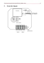
Page 31: ...Mounting and Connection Instructions RF BUS 2 wireless receiver 31 9 Connection diagram ...


