6 of 8
AII 20456 (9908)
© 1999 American Honda Motor Co., Inc - All Rights Reserved.
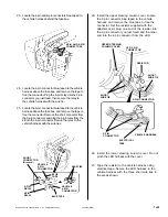
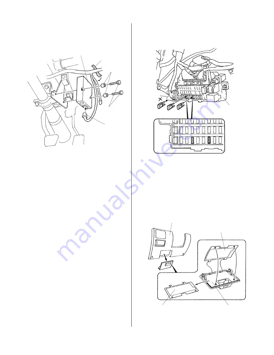
CONTROL UNIT
4 x 30 mm
BOLTS
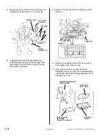
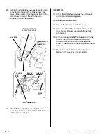
20. Remove number 3 fuse from the bottom row of the
fuse box.
(Discard.)
FUSE BOX
21. Push the two fuses from the kit into the number 3
and number 6 slots in the fuse box.
22. Remove the fuse box cover from the driver's
dashboard lower cover; then remove and discard the
existing fuse label. Attach the fuse label from the kit
to the fuse box cover.
NEW FUSE
BOX LABEL
FUSE BOX
COVER
DRIVER'S DASHBOARD
LOWER COVER
EXISTING FUSE
BOX LABEL
(Remove and discard.)
22-PIN
CONNECTOR
BLUE TAPE
(Remove.)
18. Position the control unit on the control bracket, and
install the two collars and two 4 x 30 mm bolts.
19. Locate the 22-pin connector blue-taped to the
vehicle harness, and remove the blue tape to free
the connector. Plug the 22-pin connector you just
freed into the control unit.
COLLARS


