10-2
dummyhead
dummyhead
OTHER ELECTRICAL
OTHER ELECTRICAL
OIL LEVEL SWITCH
REMOVAL/INSTALLATION
Disconnect the oil level switch connector.
Remove the camshaft (page 13-4).
• Take care not to drop the valve lifter.
ENGINE STOP SWITCH
REMOVAL/INSTALLATION
• Remove the engine stop switch only if necessary for
engine stop switch or fan cover replacement.
Remove the fan cover (page 5-2).
Straighten the tab [1] of the engine stop switch [2] and
remove the engine stop switch.
Install the engine stop switch to the fan cover aligning
its groove with the boss of the fan cover.
Bend the tab until it is fully seated on the fan cover so
the engine stop switch is held.
• The tab is used for ground terminal.
Install the fan cover (page 5-2).
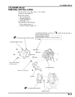
OIL LEVEL SWITCH
BOLT (6 x 12 mm) (2)
O-RING
OIL LEVEL SWITCH JOINT NUT (10 mm)
10 N·m (1.0 kgf·m, 7 lbf·ft)
[2]
[1]
Align
Summary of Contents for GP160H
Page 19: ...MEMO dummyhead dummyhead ...
Page 26: ...2 7 dummyhead dummyhead SERVICE INFORMATION Valve guide reamer 5 510 mm 07984 2000001 ...
Page 28: ...2 9 dummyhead dummyhead SERVICE INFORMATION FUEL TUBE BREATHER TUBE HIGH TENSION CORD ...
Page 39: ...MEMO dummyhead dummyhead ...
Page 40: ...4 1 4 dummytext 4 TROUBLESHOOTING BEFORE TROUBLESHOOTING 4 2 TROUBLESHOOTING 4 2 ...
Page 45: ...MEMO dummyhead dummyhead ...
Page 46: ...5 1 5 dummytext 5 FAN COVER FAN COVER REMOVAL INSTALLATION 5 2 ...
Page 49: ...6 2 dummyhead dummyhead FUEL SYSTEM FUEL SYSTEM TOOL Float level gauge 07401 0010000 ...
Page 57: ...MEMO dummyhead dummyhead ...
Page 65: ...MEMO dummyhead dummyhead ...
Page 73: ...MEMO dummyhead dummyhead ...
Page 87: ...MEMO dummyhead dummyhead ...
Page 97: ...MEMO dummyhead dummyhead ...
Page 111: ...MEMO dummyhead dummyhead ...
Page 112: ...14 1 14 dummytext 14 WIRING DIAGRAMS WIRING DIAGRAMS 14 2 ...


