


32
Chapter 1 Engine, clutch and gearbox
5 Piston ring wear is measured by removing the rings from
the piston and inserting them in the cylinder bore using the
crown of the piston to locate them approximately 25 mm (1 in)
from the top of the bore. Make sure they rest square with the
bore. Measure the end gap with a feeler gauge; if it exceeds
mm
in) the rings require renewal.
22 Examination and
cylinder barrel
1 The usual indications of a badly worn cylinder barrel and
piston are excessive oil consumption and piston slap, a metallic
rattle that occurs when there is little or no load on the engine. If
the top of the bore of the cylinder barrel is examined carefully, it
will be found that there is a ridge on the thrust side, the depth of
which will vary according to the amount of wear that has taken
place. This marks the limit of travel of the uppermost piston
ring.
2 Measure the bore diameter just below the ridge, using an
internal micrometer. Compare this reading with the diameter at
the bottom of the cylinder bore, which has not been subject to
wear. If the difference in readings exceeds 0 0 9 mm
in) it is necessary to have the cylinder rebored and to fit an
size piston and rings.
3 If an internal micrometer is not available, the amount of
cylinder bore wear can be measured by inserting the piston
without rings so that it is approximately 20 mm
in) from the
top of the bore. If it is possible to insert a 0 1 0 mm ( 0 0 0 4 in)
feeler gauge between the piston and the cylinder wall on the
thrust side of the piston, remedial action must be taken.
4 Check the surface of the cylinder bore for score marks or
any other damage that may have resulted from an earlier engine
seizure or displacement of the gudgeon pin. A rebore will be
necessary to remove any deep indentations, irrespective of the
amount of bore wear, otherwise a compression leak will occur.
5 Check the external cooling fins are not clogged with oil or
road dirt; otherwise the engine will overheat.
23 Cylinder head: valve removal, examination and renova-
tion
1 Remove each valve in turn, using a valve spring com-
pressor, and place the valves, springs, seats and collet halves in
a suitable box or bag marked to denote inlet or exhaust as
appropriate. Assemble the valve spring compressor in position
on the cylinder head, and gradually tighten the threaded portion
to place pressure on the upper spring seat. Do not exert undue
force to compress the springs, the tool should be placed under
slight load, and then tapped on the end to jar the collet halves
free. Continue to compress the springs until the collet halves
can be dislodged using a small screwdriver. Note that the valve
springs exert considerable force, and care should be taken to
avoid the compressed assembly flying apart. To this end, a small
magnet is invaluable for retrieving the collet halves, being more
delicate than fingers.
2 After cleaning the valves to remove all traces of carbon,
examine the heads for signs of pitting and burning. Examine
also the valve seats in the cylinder head. The exhaust valve and
its seat will probably require the most attention because these
are the hotter running of the two. If the pitting is slight, the
marks can be removed by grinding the seats and valves
together, using fine valve grinding compound.
3 Valve grinding is a simple task, carried out as follows:
Smear a trace of fine valve grinding compound (carborundum
paste) on the seat face and apply a suction grinding tool to the
head of the valve. With a semi-rotary motion, grind in the valve
head to its seat. It is advisable to lift the valve occasionally, to
distribute the grinding compound evenly. Repeat this operation
until an unbroken ring of light grey matt finish is obtained on
both valve and seat. This denotes the grinding operation is com-
plete. Before passing to the next operation, make quite sure that
all traces of the grinding compound have been removed from
both the valve and its seat and that none has entered the valve
guide. If this precaution is not observed, rapid wear will take
place, due to the abrasive nature of the carborundum base.
4 When deeper pit marks are encountered, it will be
necessary to use a valve refacing machine and also a valve seat
cutter, set to an angle of 45°. Never resort to excessive grinding
because this will only pocket the valve and lead to reduced
engine efficiency. If there is any doubt about the condition of a
valve, fit a new replacement.
5 Examine the condition of the valve collets and the groove
on the valve in which they seat. If there is any sign of damage,
new replacements should be fitted. If the collets work loose
whilst the engine is running, a valve will drop in and cause
extensive damage.
6 Measure the valve stems for wear, making reference to the
tolerance values given in the Specifications Section of this
Chapter.
7 Check the free length of the valve springs against the list of
tolerances in the Specifications. If the springs are reduced in
length or if there is any doubt about their condition, they should
be renewed.
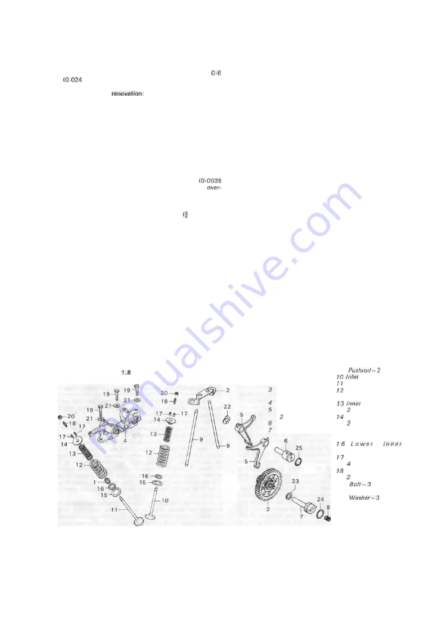
Fig.
Valve gear - component parts
Exhaust valve
stem seal
Pushrod guide
plate
Cam and gear
assembly
Rocker assembly
Cam follower —
off
Pivot shaft
Cam gear shaft
8 Spring
9
off
valve
Exhaust valve
Outer valve spring -
2 off
valve spring -
off
Upper spring seat —
off
1 5 L owe r outer
spring seat -2 off
spring seat — 2 off
Collet halves -
off
Adjusting screw -
off
19
off
20 Locknut-2 off
21
off
22 Wave washer
23 Washer
24 0 ring
25 0 ring


