Please read this manual carefully before using the product and keep it in a
safe place for reference.
This product was constructed up to standard and in compliance with regulations relating to
electrical equipment and must be installed by technically qualified personnel in accordance
with all regulatory requirements. The manufacturer assumes no responsibility for damage to
persons or property resulting from failure to observe the instructions contained in this booklet.
PRECAUTIONS FOR INSTALLATION, USE & MAINTENANCE
•
The unit is only suitable for installation in single or two storey dwellings, with a “cold roof” construction, where no storey is 4.5 metres or more
above ground level.
•
The device should not be used for applications other than those specified in this manual.
•
After removing the product from its packaging, verify its condition. In case of doubt, contact a qualified technician. Do not leave packaging
within the reach of small children.
•
Do not touch the appliance with wet or damp hands / feet.
•
This appliance can be used by children aged from 8 years and above and persons with reduced physical, sensory or mental capabilities or lack
of experience and knowledge if they have been given supervision or instruction concerning use of the appliance in a safe way and understand
the hazards involved.
•
Children should be supervised to ensure that they do not play with the device.
•
WARNING: Never use the fan unit without the provided flexible ducting, air valve and filter attached.
•
WARNING: In order to avoid overheating, do not obstruct the airflow into and out of the fan unit.
•
Do not use the product in the presence of flammable vapours, such as alcohol, insecticides, gasoline, etc.
•
If any abnormalities in operation are detected, disconnect the device from the mains supply and contact a qualified technician immediately.
Use original spare parts only for repairs.
•
The electrical system to which the device is connected must comply with applicable regulations.
•
Before connecting the product to the power supply or the power outlet, ensure that:
The data plate (voltage and frequency) correspond to those of the electrical mains.
The electrical power supply / socket is adequate for maximum device power. If not, contact a qualified technician.
•
The unit is designed for use in ambient temperatures of -10 °C up to +60 °C and up to 90% Relative Humidity.
•
Do not leave the device exposed to atmospheric agents (rain, sun, snow, etc.).
•
Do not immerse the device or its parts in water or other liquids.
•
Only turn off the power supply to the unit whenever a malfunction is detected or in the case of inspection, cleaning or maintenance. Prolonged
and/or repeated power interruption to the unit (any period more than 72 hours) can create a health and safety hazard, damage components and
will invalidate any warranty.
•
For installation, an omnipolar switch should be incorporated in the fixed wiring, in accordance with the wiring regulations, to provide a full
disconnection under overvoltage category III conditions (contact opening distance equal to or greater than 3mm).
•
Do not obstruct the fan inlet filter or supply air valve to ensure optimum air passage.
•
Ensure adequate air supply into the loft space in order to ensure proper device operation.
•
If the environment in which the product is installed also houses a fuel-operating device (water heater, methane stove etc., that is not a “sealed
chamber” type), it is essential to ensure adequate air intake, to ensure good combustion and proper equipment operation.
•
Install the product so that the impeller is not accessible from the air outlet side as verified by contact with the Test Finger (test probe “B” of the
norm EN61032) in compliance with the current safety regulations.
Installation &
Maintenance Manual
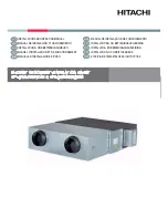
HV PIV LOFT
Positive Input Ventilation Unit