44
45
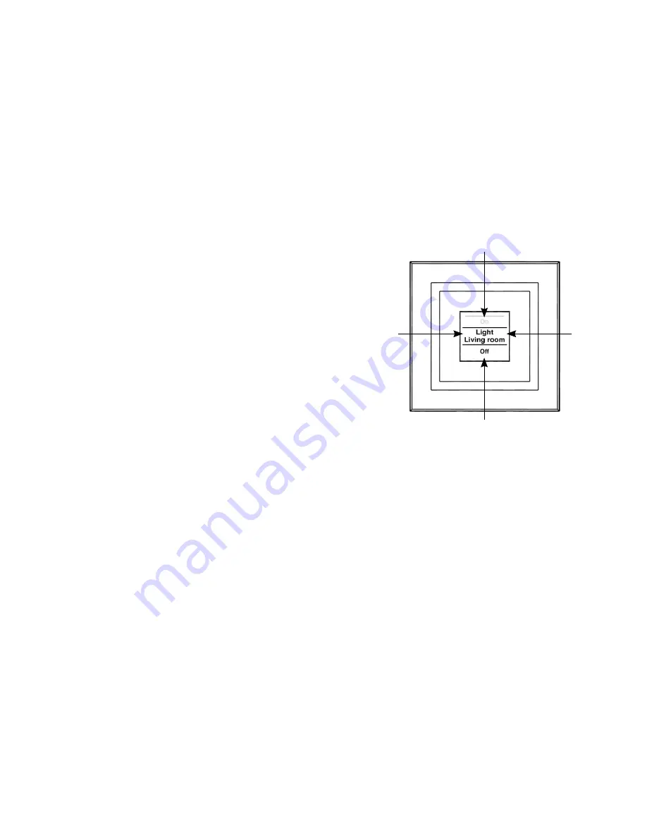
actuator and the room. In the previous figure, an ac
-
tuator has been called “Light” and the room has been
named “Living room”. These names can be defined
in accordance with individual requirements (refer to
Section 8.3).
The available switching options are shown in the upper
(C)
and lower
(E)
areas. An actuator to be used for
controlling lights would have the switching options
“On” and “Off” assigned to it. If KeyMatic were to be
selected as the actuator, the switching options “Un-
lock” and “Lock” would be shown instead, for example
(refer also to Section 10).
Switching operations are confirmed on the display. If
an action (such as switching on the light) is performed
via the display push-button, the display text will initially
be orange to indicate that the associated command
is being transmitted. If the display push-button recei-
ves feedback from the actuator confirming that the
light has been switched on successfully, the text will
immediately change to green. If the light could not be
switched on for any reason, this will be indicated by
the text changing to red.
4.2. General operation and menu
F
H
G
I
The rocker on the display push-button can be pressed
in four different directions. A general distinction is
also made between pressing and releasing the button
(button pressed for under 4 seconds) and pressing
and holding down the button (button pressed for more
than 4 seconds). Press the left
(F)
or right
(H)
of the
button to select one of the various taught-in devices or
channels. Up to 10 channels (positions 1 to 10) can be
assigned. Pressing the button at the top
(I)
or bottom
(G)
triggers an action. Usually the top
(I)
switches a
device on and the bottom
(G)
switches it off. Pressing