background image

9

HOMEDEPOT.COM/HOMEDECORATORS

Please contact 1-800-986-3460 for further assistance.

Assembly - Hanging the Fan (continued)

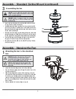
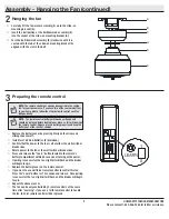
Hanging the fan


Carefully lift the fan-motor assembly (E) up to the slide-on 
mounting bracket (A).


Insert the ball portion of the ball/downrod assembly (B) 
into the socket of the slide-on mounting bracket (A).


Turn the ball/downrod assembly (B) clockwise until it is 
seated with the tab of the slide-on mounting bracket (A) 
aligned with the slot in the ball.

2

Preparing the remote control

3


Remove the battery cover by pressing firmly on the arrow and 

sliding the cover off.


Install two 1.5V AAA batteries (K) (included).


Confirm that the power to the fan is off at either the wall switch or 

breaker box.


Return power to the fan at the wall switch or breaker box.


Press and release the “Learn” button located in the remote’s 

battery compartment within 30 seconds of turning on the power.


If pairing is successful, the fan’s light kit will flash and the blades 

will begin to spin.


Replace the battery cover on the remote control.


If you want to use a different remote control to control this fan,  

Press the “Learn” button for 10 seconds and release.  Once pairing 

is successful, the fan’s light kit will flash and the blades will begin 

to spin.


Repeat the above process.


The fan can be only controlled by 3 remote controls at the same 

time after “Learning”, if you use a forth remote control to handle 

the fan, the first remote control will be replaced .

NOTE:

 The remote control has already been paired to the ceiling 

fan for your convenience. If you have two of the same model fans 

in your home, please follow the steps below to control each fan 

independently.

NOTE:

  The remote control battery will weaken with age and 

should be replaced before leaking takes place, as this will damage 

the remote control. Dispose of used battery properly and keep the 

battery out of the reach of children.

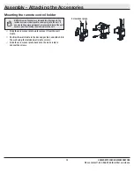
C

D

B

JJ  

A

E

0

1

0

1

Summary of Contents for 60-DOWN

Page 1: ...esigned to enhance your home Visit us online to see our full line of products available for your home improvement needs Thank you for choosing Home Decorators Collection Item xxxx xxx xxx Model 56043 UL Model 60 DOWN USE AND CARE GUIDE DOWNEY 60 INCH CEILING FAN To view an instructional video on how to install this product 1 Go to www homedepot com and enter either the Item or Model number found i...

Page 2: ...eferred to as flanges during assembly or after installation Do not insert objects in the path of the blades WARNING To reduce the risk of fire or electric shock do not use this fan with any solid state speed control device WARNING Electrical diagrams are for reference only If you are using a light kit refer to the light kit instructions manual to make the electrical connections Optional use of any...

Page 3: ...ver any changes in brass finish including rusting pitting corroding tarnishing or peeling Brass finishes of this type give their longest useful life when protected from varying weather conditions A certain amount of wobble is normal and should not be considered a defect Servicing performed by unauthorized persons shall render the warranty invalid There is no other express warranty Interline hereby...

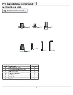
Page 4: ...crews 25 BB Decorative blade attachment screws 13 CC Blade arm screws 13 DD Plastic Wire Connector 3 EE Locking pin 1 FF Hanger Pin 1 GG Hex key 1 Pre Installation continued HARDWARE INCLUDED NOTE Hardware not shown to actual size GG FF EE DD BB AA CC ...

Page 5: ... E Fan motor assembly 1 F Blade 6 Part Description Quantity G Blade arm 6 H Decorative blade 6 I Bottom plate 1 J Receiver 1 K Remote control 1 L 66 in extension wire 1 M 12 in extension wire 1 N Battery 2 IMPORTANT This product and or components are governed by one or more of the following U S Patents 5 947 436 5 988 580 6 010 110 6 046 416 6 210 117 and other patents pending Pre Installation con...

Page 6: ...et box and support structure must be securely mounted and capable of reliably supporting a minimum of 35 lbs 15 9 kg Use only UL listed outlet boxes marked Acceptable for fan support of 35 lbs 15 9 kg or less Do not use a plastic outlet box The illustrations below show three different ways to mount the outlet box If the canopy touches the downrod then remove the decorative canopy bottom cover and ...

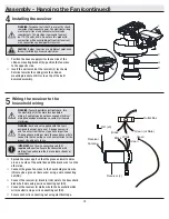
Page 7: ...ting the top of the fan motor assembly E by connecting the molded adaptor plugs together Route the wires through the decorative motor collar cover D and then the center of the canopy bottom cover JJ Make sure the opening of canopy C is on top and insert the ball downrod B through the canopy C Route the wires exiting the top of the fan motor assembly E through the downrod as shown 2 1 NOTE The fan ...

Page 8: ...Assembly Standard Ceiling Mount continued Assembling the fan Loosen but do not remove the setscrew KK on the collar PP on top of the fan motor assembly E Install the downrod B by inserting it into the motor collar PP and turning it clockwise until the holes at the bottom of the ball downrod assembly B align with the holes in the collar on top of the fan motor assembly E Carefully insert the hanger...

Page 9: ... within 30 seconds of turning on the power If pairing is successful the fan s light kit will flash and the blades will begin to spin Replace the battery cover on the remote control If you want to use a different remote control to control this fan Press the Learn button for 10 seconds and release Once pairing is successful the fan s light kit will flash and the blades will begin to spin Repeat the ...

Page 10: ...g If you feel you do not have enough electrical wiring knowledge or experience contact a licensed electrician WARNING Each wire nut supplied with this fan is designed to accept up to one 12 gauge house wire and two wires from the fan If you have larger than 12 gauge house wiring or more than one house wire to connect to the fan wiring consult an electrician for the proper size wire nuts to use IMP...

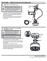
Page 11: ...g MM Green 1 2 3 4 O N D I P L Mounting the fan motor assembly standard mount 7 WARNING When using the standard ball downrod mounting the tab in the ring at the bottom of the mounting bracket must rest in the groove of the hanger ball Failure to properly seat the tab in the groove could cause damage to the wiring NOTE The magnet is pre attached on the canopy bottom cover for you to remove and inst...

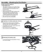
Page 12: ...the threaded post LL at the base of the fan until tight CC GG I Attaching the blades to the blade arms 1 Attach a blade F to the blade arm G by aligning the holes on the blade arm G with the holes on blades F inserting the screws AA into the holes in the blade arm G and through the blade F Tighten each screw securely Attach the support plate to the blade assembly by aligning the holes on the blade...

Page 13: ... wall cradle in the desired position and attach it to the wall using the included wall cradle screws Slide the screw cover plate back onto the wall cradle to conceal the screws Screw cover plate NOTE Screw wall anchors are included for extra support The included screws are designed to screw easily into the wall If you would like a more permanent or secure hold install the wall anchors prior to att...

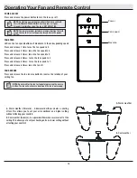
Page 14: ...t setting when turned on via the power button FAN REVERSE Press and release the fan reverse button to reverse the rotation of your ceiling fan A Warm weather Forward A downward airflow creates a cooling effect This allows you to set your air conditioner on a higher setting without affecting your comfort B Cool weather Reverse An upward airflow moves warm air off of the ceiling This allows you to s...

Page 15: ...otor fans Because of the fan s natural movement some connections may become loose Check the support connections brackets and blade attachments twice a year Make sure they are secure It is not necessary to remove the fan from the ceiling Clean your fan periodically to help maintain its new appearance over the years Do not use water when cleaning as this could damage the motor or the wood or possibl...

Page 16: ...blems missing parts Before returning to the store call Home Depot Customer Service 8 a m 7 p m EST Monday Friday 9 a m 6 p m EST Saturday 1 800 986 3460 HOMEDEPOT COM HOMEDECORATORS Retain this manual for future use ...

Reviews: