background image

11

HOMEDEPOT.COM/HOMEDECORATORS

Please contact 1-800-986-3460 for further assistance.

Assembly - Assembling the Fan Without the  Light Kit 

Attaching the light kit fitter assembly


In order to use the fan without light kit, remove the switch 
cup cover (WW) from the top of the light kit fitter assembly 
(D) by removing the center hex nut inside the switch cup 
cover (WW) off of the threaded nipple on the top of the light 
kit fitter assembly (D).


 Press the plastic plug (CC) into the center hole of the switch 
cup cover (WW).


Remove the three screws (TT) on the switch cup cover (WW).


Align the three holes in the switch cup cover (WW) with the 
three holes in the switch cup of the fan-motor assembly (B). 
Make sure the notch in the switch cup cover (WW) clears the 
slide switch in the switch cup of the fan-motor assembly (B).


Re-install the three screws (TT) that were removed in first 
step to secure the switch cup cover (WW).

7

CAUTION:

  To reduce the risk of electric shock, disconnect 

the electrical supply circuit to the fan before installing the 

light kit.

WW

TT

B

CC

DD

Operation

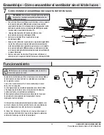
Turn on the power and check the operation of the fan. The pull 
chain controls the fan speeds as follows:
1 pull - High, 2 pulls - Medium-High, 3 pulls Medium-Low, 4 pulls 
Low, 5 pulls - off
The appropriate speed settings for warm or cool weather depends 
on factors such as the room size, ceiling height, and number of 
fans.
The slide switch (XX) controls the direction of the blades: forward 
(switch left) or reverse (switch right)

Warm weather - (Forward) A downward airflow creates a cooling ef-
fect. This allows you to set your air conditioner on a warmer setting 
without affecting your comfort.
Cool weather - (Reverse) An upward airflow moves warm air off of 
the ceiling. This allows you to set your heating unit on a cooler set-
ting without affecting your comfort.

NOTE:

 Wait for the fan to stop before reversing the direction of the 

blade rotation.

XX

XX

Summary of Contents for 51576

Page 1: ...M HOMEDECORATORS THANK YOU We appreciate the trust and confidence you have placed in Home Decorators Collection through the purchase of this ceiling fan We strive to continually create quality products designed to enhance your home Visit us online to see our full line of products available for your home improvement needs Thank you for choosing Home Decorators Collection Item 1000 XX XXX Model 5157...

Page 2: ...es Refer to the instructions packaged with the light kits and switches for proper assembly 9 After making electrical connections spliced conductors should be turned upward and pushed carefully up into the outlet box The wires should be spread apart with the grounded conductor and the equipment grounding conductor on one side of the outlet box 10 All setscrews must be checked and retightened where ...

Page 3: ...ccessories is not covered by this warranty Because of varying climatic conditions this warranty does not cover any changes in brass finish including rusting pitting corroding tarnishing or peeling Brass finishes of this type give their longest useful life when protected from varying weather conditions A certain amount of wobble is normal and should not be considered a defect Servicing performed by...

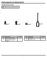
Page 4: ...lastic wire connector 3 BB Extra blade bracket hardware screw and lockwasher 1 Part Description Quantity CC Plastic plug 1 DD Pull chain 2 HARDWARE INCLUDED NOTE Hardware not shown to actual size AA BB DD CC Pre Installation continued ...

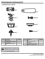
Page 5: ...er assembly 1 Part Description Quantity E Blade 5 F Blade bracket with pre installed screws 5 G Glass bowl with trim ring 1 H CFL bulbs 14 Watt maximum 3 IMPORTANT This product and or components are governed by one or more of the following U S Patents 5 947 436 5 988 580 6 010 110 6 046 416 6 210 117 and other patents pending PACKAGE CONTENTS A C B D G F E H Pre Installation continued ...

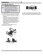
Page 6: ... instructions Disconnect the power by removing the fuses or turning off the circuit breakers Secure the outlet box directly to the building structure Use the appropriate fasteners and materials The outlet box and support structure must be securely mounted and capable of reliably supporting 35 lbs 15 9 kg Use only UL Listed outlet boxes marked Acceptable for Fan Support of 35 lbs 15 9 kg or less Do...

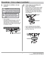
Page 7: ... motor assembly B with the hook on the mounting plate A so that it is securely suspended Then connect the wiring to your fan according to step 3 Making the Electrical Connections Once the wiring is completed lift the fan motor assembly B Align the holes in the mounting plate A with the pre attached screws HH on the motor bracket II Securely tighten the screws HH 2 1 A EE FF GG B A A B HH II NOTE F...

Page 8: ...with your fan Secure the connectors with electrical tape and ensure there are no loose strands or connections WARNING Each wire not supplied with this fan is designed to accept up to one 12 gauge house wire and two wires from the fan If you have larger than 12 gauge house wiring or more than one house wire to connect to the fan wiring consult an electrician for the proper size wire nuts to use Con...

Page 9: ...until it engages in the locking mechanism SS Make sure the locking mechanism SS at the rear of the blade bracket F springs upward and butts against the edge of the blade E indicating a secure connection Visually inspect the top of the blade bracket F to ensure the locking mechanism SS is securely in place Repeat this procedure for the remaining blades E 5 B F QQ Attaching the blades to the blade b...

Page 10: ... into the light bulb sockets Position the glass bowl G and direct the fan pull chain through the side hole of the bottom cover Direct the light pull chain through the hole in the bottom cover V V and finial UU guide them over the threaded nipple and tighten the finial UU securely Attach the pull chain extensions DD provided to the light pull chain and fan pull chain 7 8 CAUTION To reduce the risk ...

Page 11: ...emoved in first step to secure the switch cup cover WW 7 CAUTION To reduce the risk of electric shock disconnect the electrical supply circuit to the fan before installing the light kit WW TT B CC DD Operation Turn on the power and check the operation of the fan The pull chain controls the fan speeds as follows 1 pull High 2 pulls Medium High 3 pulls Medium Low 4 pulls Low 5 pulls off The appropri...

Page 12: ...t on the ceiling Rotate the fan until the next blade is positioned for measurement and measure from the same point on each blade to the ceiling Repeat for each blade Any measurement deviation should be within 1 8 in Run the fan for ten minutes Because of the fan s natural movement some connections may become loose Check the support connections brackets and blade attachments twice a year Make sure ...

Page 13: ...uestions problems missing parts Before returning to the store call Home Depot Customer Service 8 a m 6 p m EST Monday Friday 1 800 986 3460 HOMEDEPOT COM HOMEDECORATORS Retain this manual for future use ...

Page 14: ... HOMEDECORATORS GRACIAS POR TU COMPRA Apreciamos la confianza que has depositado en Home Decorators Collection al comprar este ventilador de techo Nos esforzamos para continuamente crear productos de calidad diseñados para mejorar tu hogar Visítanos por Internet para ver nuestra línea completa de productos disponibles para las necesidades de mejoras de tu hogar Gracias por elegir Home Decorators C...

Page 15: ...res para obtener información sobre el ensamblaje adecuado 9 Después de concluir las conexiones eléctricas debes voltear los conductores empalmados hacia arriba y meterlos con cuidado en la caja eléctrica Los cables deben estar separados con el cable a tierra y el conductor a tierra del equipo hacia uno de los lados de la caja eléctrica 10 Todos los tornillos de fijación deben ser verificados y aju...

Page 16: ...alación de cualquier accesorio no están cubiertos bajo esta garantía Debido a que las condiciones climáticas pueden variar esta garantía no cubre ningún cambio en el acabado en bronce incluyendo óxido perforación corrosión manchas o descascaramiento Los acabados en bronce de este tipo tienen una vida útil más prolongada cuando se los protege de las condiciones climáticas cambiantes Es normal ciert...

Page 17: ... BB Herrajes adicionales para montaje de aspas tornillo y arandela de seguridad 1 Pieza Descripción Cantidad CC Tapón plástico 1 DD Interruptor de cadena 2 HERRAJES INCLUIDOS NOTA No se muestra el tamaño real de los herrajes AA BB DD CC Preinstalación continuación ...

Page 18: ...de luces 1 Pieza Descripción Cantidad E Aspa 5 F Soporte de aspa con tornillos preinstalados 5 G Tazón de vidrio con aro de moldura 1 H Bombillas CFL máximo de 14 W 3 IMPORTANTE Este producto o sus componentes están protegidos por una o más de las siguientes patentes de los EE UU 5 947 436 5 988 580 6 010 110 6 046 416 6 210 117 y otras patentes pendientes CONTENIDO DEL PAQUETE A C B D G F E H Pre...

Page 19: ...gía retirando los fusibles o apagando los cortacircuitos Asegura la caja eléctrica directamente a la estructura de la edificación Usa sujetadores y materiales apropiados La caja eléctrica y la estructura de soporte deben montarse de forma segura y tener capacidad para sostener de manera confiable 15 9 kg Usa solamente cajas eléctricas aprobadas por UL marcadas como apropiada para sostener ventilad...

Page 20: ...motor del ventilador B con el gancho de la placa de montaje A para que quede suspendido de forma segura Luego conecta el cableado a tu ventilador según lo indica el paso 3 Cómo hacer las conexiones eléctricas Levanta el ensamblaje del motor del ventilador B Alinea los orificios de la placa de montaje A con los tornillos preinstalados HH en el soporte del motor II Aprieta bien los tornillos HH 2 1 ...

Page 21: ...ectricista y asegúrate de que no haya conexiones o cables sueltos ADVERTENCIA Cada cable no suministrado con este ventilador está diseñado para aceptar un máximo de un solo circuito eléctrico doméstico de calibre 12 y dos cables del ventilador Si tienes un cableado doméstico superior a calibre 12 o más de un cable doméstico para conectar al cableado del ventilador consulta a un electricista para c...

Page 22: ...asta se acople al mecanismo de cierre SS Asegúrate de que el mecanismo de cierre SS en la parte posterior del soporte del aspa F se eleve y haga tope contra el borde del aspa E lo que indicará una conexión segura Revisa la parte superior del soporte del aspa F para garantizar que el mecanismo de cierre SS esté asegurado en su lugar Repite este procedimiento para las aspas restantes E 5 B F QQ Cómo...

Page 23: ...tricidad apagada instala las tres bombillas CFL H enroscándolas en los portabombillas Coloca el tazón de vidrio G y pasa la cadena del interruptor del ventilador a través del orificio lateral en la cubierta inferior Pasa la cadena del interruptor de las luces a través del orificio en la cubierta inferior V V y el remate UU pásalos sobre la boquilla roscada y ajusta bien el remate UU Instala las ex...

Page 24: ...ron retirados en el primer paso para asegurar la cubierta de la caja del interruptor WW 7 PRECAUCIÓN Para disminuir el riesgo de descarga eléctrica desconecta el circuito de energía del ventilador antes de instalar el kit de luces WW TT B CC DD Funcionamiento Enciende la electricidad y verifica el funcionamiento del ventilador El interruptor de cadena controla las velocidades del ventilador de la ...

Page 25: ...bre la punta de una de las aspas Mide desde un punto en el centro de cada aspa a un punto en el techo Rota el ventilador hasta que la siguiente aspa esté posicionada para medir y mide desde el mismo punto en cada aspa hasta el techo Repite para cada aspa Las desviaciones de la medición deben estar dentro de un rango de 3 mm Enciende el ventilador durante diez minutos Debido al movimiento natural d...

Page 26: ...as faltantes Antes de regresar a la tienda llama al servicio al cliente de The Home Depot de lunes a viernes de 8 a m a 6 p m hora estándar del Este 1 800 986 3460 HOMEDEPOT COM HOMEDECORATORS Conserva este manual para uso futuro ...

Reviews: