background image

EXPLOSION VIEW

No.

Description

Qty.

No.

Description

Qty.

1

Rear support tube

1

17

Screw M10*20

2

2

Front support tube

1

18

Screw M10*70

3

3

Adjustable support tube

1

19

Screw M10*65

2

4

Leg holder for fixing

1

20

Washer

16

5

Handle tube (Left)

1

21

Screw M6 *15

4

6

Handle tube (Right)

1

22

Washer

4

7

Pipe (Leg fixation)

1

23

Safety pin

1

8

Front stand

1

24

Nut M10

7

9

Rear stand

1

25

Plastic cover

2

10

Adapter plate

1

26

Screw cover

16

11

Padded cushion

1

27

Plastic cover

1

12

Foam roller

2

28

Plastic cover

1

13

Grip foam

2

29

Tool

2

14

Adjusting knob

1

30

Screw M10 *60

2

15

Bolt

1

31

Blister packing

1

16

Stand cover

4

10

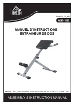
Summary of Contents for A91-181

Page 1: ...ASSEMBLY INSTRUCTION MANUAL INalb010_FR_EN A91 181 IMPORTANT RETAIN FOR FUTURE REFERENCE READ CAREFULLY MANUEL D INSTRUCTIONS ENTRA NEUR DE DOS...

Page 2: ...5 4 6 Tube de poign e Droite 1 22 Rondelle 4 7 Tube fixation des jambes 1 23 Goupille de verrouillage 1 8 Support avant 1 24 crou M10 7 9 Support arri re 1 25 Chapeau en plastique 2 10 Plaque d adapta...

Page 3: ...VIS 21 M6 15 4PCS RONDELLE 22 4PCS RONDELLE 20 16PCS VIS 17 M10 20 2PCS VIS 30 M10 60 2PCS OUTIL 29 2PCS VIS 19 M10 65 2PCS VIS 18 M10 70 3PCS ECROU 24 M10 7PCS 3...

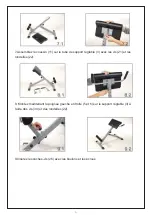
Page 4: ...e sous la t te du boulon et l crou A l arri re du tube de support avant fixez la vis 17 avec une rondelle 20 2 Fixez le support arri re 9 avec la vis 19 et deux rondelles 20 et l crou 24 au niveau du...

Page 5: ...r fixation 4 sur le tube de support avant 2 avec la plaque d adaptateur 10 et les vis 18 les rondelles 20 et les crous 24 5 Branchez le tube 7 dans le trou sur le porte jambe pour fixation 4 et ins re...

Page 6: ...de support r glable 3 avec les vis 21 et les rondelles 22 8 Montez maintenant la poign e gauche et droite 5 et 6 sur le support r glable 3 l aide des vis 30 et des rondelles 22 9 Ins rez les caches v...

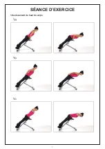
Page 7: ...S ANCE D EXERCICE 1 Soul vement du haut du corps 7...

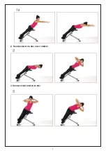
Page 8: ...2 Soul vement du dos avec rotation 3 Soul vement lat ral du dos 8...

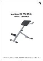
Page 9: ...IMPORTANT RETAIN FOR FUTURE REFERENCE READ CAREFULLY MANUAL INSTRUCTION BACK TRAINER 9...

Page 10: ...Washer 16 5 Handle tube Left 1 21 Screw M6 15 4 6 Handle tube Right 1 22 Washer 4 7 Pipe Leg fixation 1 23 Safety pin 1 8 Front stand 1 24 Nut M10 7 9 Rear stand 1 25 Plastic cover 2 10 Adapter plate...

Page 11: ...11...

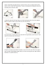
Page 12: ...lled under the bolt head and the nut On the back of the front support tube attach the screw 17 with washer 20 2 Mounting the rear pedestal 9 with the screw 19 comprises two washers 20 and the nut 24 a...

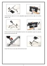
Page 13: ...mp 4 on the front support tube 2 with the Adapter plate 10 and the screws 18 washers 20 and the nuts 24 5 Plug the tube 7 into the hole on the bracket for the leg fixation 4 and insert a Foam roller 1...

Page 14: ...the adjustable support 3 with the screws 21 and the Washers 22 8 Now mount the left and right handle 5 and 6 on the adjustable support 3 using the screws 30 and washers 22 9 Insert the screw covers 2...

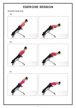
Page 15: ...EXERCISE SESSION 1 Back lift upper body 15...

Page 16: ...2 back lift with rotation 3 Lateral back lift 16...

Page 17: ......

Reviews: