


EngliSH | 27
5.3. Commissioning
This chapter contains all important instructions for oper-
ating personnel for safe commissioning and operation of
the machinery. The following must be complied with and
checked:
•
Type of installation
•
Operation mode
•
Minimal submersion in water / maximum submersion
depth
After a longer downtime these points must also be
checked and detected defaults must be repaired!
The operation and maintenance manual must
always be kept with the machinery, or in a dedicated
place where it is accessible for the entire operating
personnel.
The following points must be taken into account to avoid
personal and material damage when
troubleshooting machinery failures:
The commissioning of the machinery must only
be carried out by qualified and trained personnel in
compliance with the safety regulations.
•
All personnel that is working on the machinery must
have received, read and understood the operating
instructions.
•
Activate all safety equipment and emergency
switch-offs before commissioning.
•
Electrotechnical and mechanical settings must only
be carried out by specialists.
•
This machinery is only suitable for the use under the
indicated operating conditions.
5.4. Preparatory work
The machinery was constructed and fitted according to
the latest technology, so that it works for a long time and
reliably under normal operating conditions. This requires
however that you comply with all requirements and infor-
mations. Small oil leakages of the floating ring seals on
delivery are not problematic, but they must be removed
before lowering/immersion into the medium.
Please check the following points:
•
Cable run - no loops, slightly tightened
•
Check temperature of the medium and submersion
depth - see machinery data sheet
•
If a tube is used for pressure, this must be rinsed with
clear water so that no deposits lead to obstruction
•
The pump pit must be cleaned for wet installation
•
The pressure-sided and suction-sided pipework
system must be cleaned and all gate valves must be
opened
•
The pump casing must be flooded, e.g. it must be
filled completely with the medium and it must not
contain an air. The de-aeration can be carried out by
means of suitable venting devices in the system or, if
available, by air-vent screws on the pressure socket
•
Check accessories, pipework, suspension devices for
firm and correct fitting
•
Check available level controls/protection against dry
run
5.5. Electrical system
The respective local and VDE regulations must be com-
plied with when choosing and installing the electrical
leads as well as connecting the motor.
Electric shock hazard!
Faulty dealing with current may jeopardize your life!
All pumps with free cable ends must be connected by a
qualified electrician.
5.6. Motor protection
Single phase motor
Pumps with 230 V/single phase motors are provided with
an operation capacitor on delivery.
5.7. Switch-on types
Switch-on types with plug
Insert the plug into the socket provided for.
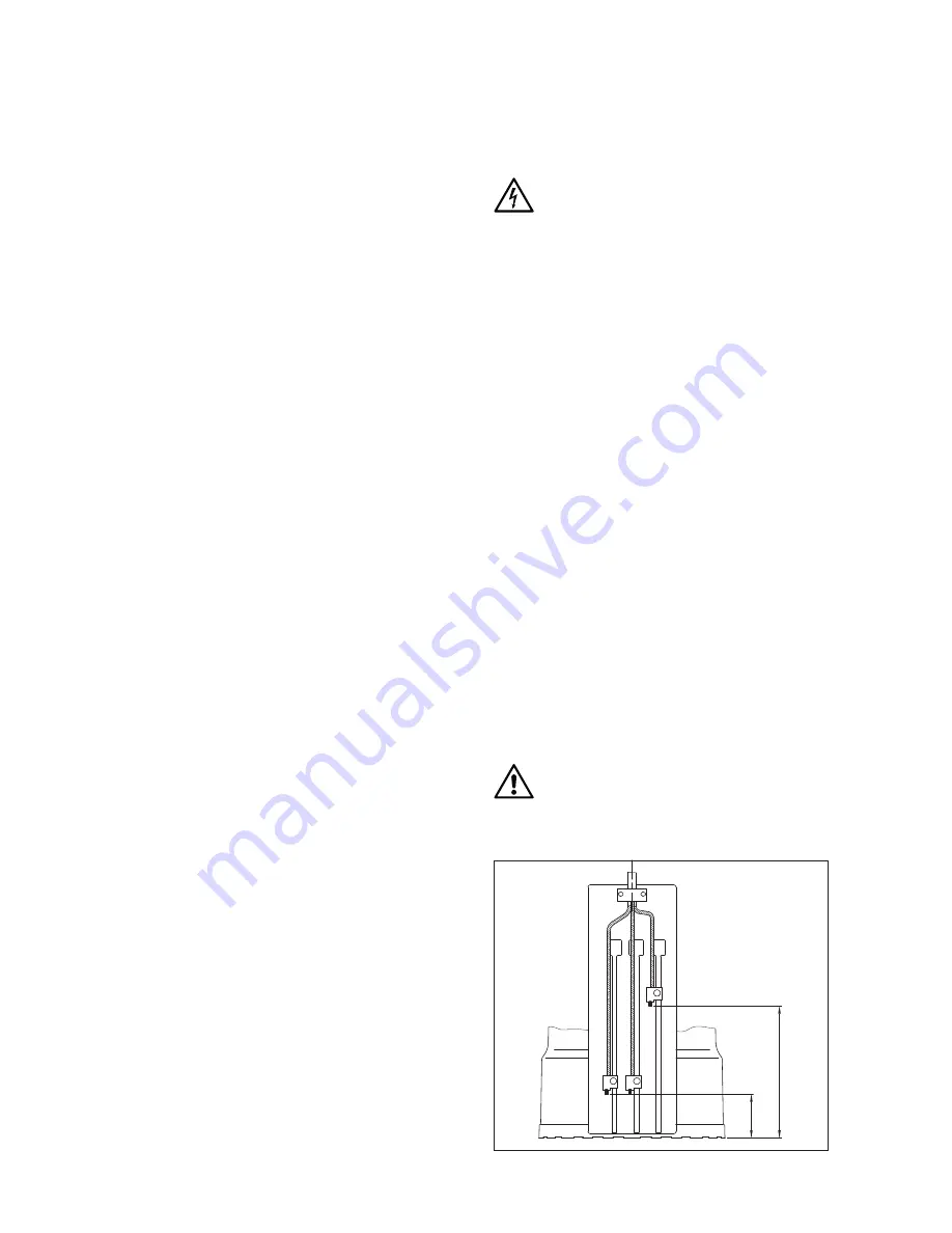
Adjustable humidity sensor switch for Type C238 WS3
The pumps are equipped with an integrated moisture
sensor. On delivery, the pump turns on at a water level of
120 mm and turns of again at 40 mm. To adjust switch-on
and switch-off points, open the black box on the side of
the pump. To do this, unscrew the two screws and pull the
black cover upwards. You will now see three sensors. You
can move them up and down. Undo the screw, move the
sensor to the new position and tighten the screw again.
With the Sensor 3, you can change the starting point of
the pump. This can be positioned between 5 mm and 145
mm. With Sensor 2, you can set the switch-off point. This
can be positioned between 1 mm and 40 mm.
The Sensor 1 must always correspond with the Sensor 2.
It must never be above the middle sensor. This is structur-
ally ensured by a stop on Sensor 2. If the Sensor 1 and 2
are in the lowest position, the pump pumps the water up
to a residual amount of 1 mm. After setting the sensors,
the black cover must be mounted with the two screws.
If the sensors were removed with the bracket for
cleaning or maintenance work, it is important to en-
sure that they are remounted in the correct order.
The sensors may not be switched out under any
circumstances.
ST
AR
T
STOP
TOT
AL
120 mm
40 mm
Summary of Contents for C237 W3
Page 47: ...FrancAIS 47 Notizen Notes...
Page 62: ...Notizen Notes...


