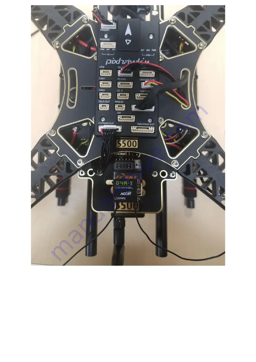
background image


Figure 30 


Step 10: Assembling the Battery Mount to the frame.  

For this we will need the M2 5X6 screws and the battery mount see Figure 31. Insert the 
long rods to the small rings see Figure 32 and 33. Attach that to the frame, make sure all 
four sides are aligned to insert the screws, see Figure 34. Assemble the small plate to the 
legs, see Figure 35 screw on all four sides. The final step is to attach the plate to the, see 
figure 36. 

Summary of Contents for Pixhawk 4 S500 V2 Basic Kit

Page 1: ...ent PM02 Assembled ARM adopts high strength plastics Motors 2216 KV880 V2 Update Propeller 1045 V2 Update Pixhawk4 GPS Fully assembled Power Management Board with ESCs 433MHz Telemetry Radio 915MHz Te...

Page 2: ...soldering iron The image below shows both frames and electronic components...

Page 3: ...n Quantity Wheelbase 480mm 1 Arms 4 Set of Landing Gear 2 M3 8 screws 18 M2 5 6 screws 24 Battery Straps 1 Propeller 1045 V2 Update 1 Pixhawk 4 Package Details Items Package Pixhawk 4 1 Pixhawk4 GPS M...

Page 4: ...able 1 SBUS receiver cable 1 USB cable 1 X type folding pedestal mount 1 70mm 140mm carbon rod standoff 2 6 3 2 54mm pitch Horizontal Pin 1 8 3 2 54mm pitch Horizontal Pin 2 Foam Set 1 Pixhawk4 Quick...

Page 5: ...s 2216 KV880 V2 Update 4 Pixhawk 4 GPS 1 Fully assembled Power Management Board with ESCs 1 433MHz Telemetry Radio 915MHz Telemetry Radio 1 Tools Needed 1 5 mm Hex screwdriver 2 0 mm Hex screwdriver 2...

Page 6: ...nutes installing the autopilot and configuring the airframe in QGroundControl Frame assembly Step 1 Assembling the Landing Gear We are going to start by assembling the landing gear to the vertical pol...

Page 7: ...anagement Board to the landing gear Screw the landing gear with a vertical pole to the Fully assembled Power Management Board The Board has 4 holes see Figure 3 arrows use the M3X8 screws a total of 8...

Page 8: ...Figure 3...

Page 9: ...Management Board Attach the arm to the Power Management Board see Figures 6 and 7 Use M2 5X6 screws a total of 2 in each arm Insert the screws from the bottom of the plate see Figure 8 Make sure the E...

Page 10: ...Figure 6...

Page 11: ...Figure 7...

Page 12: ...Figure 8...

Page 13: ...e PWM to the Power Management Board Connect the 10 to 10 pin cable PWM to the 8 3 2 54mm pitch Horizontal Pin see Figure 10 Cut a piece of 3M Tape and attach to the bottom of the Horizontal Pin see Fi...

Page 14: ...Figure 10...

Page 15: ...Figure 11...

Page 16: ...Figure 12...

Page 17: ...and the 4 arms Mount the motors in each arm put the screw through the bottom of the arm see Figures 14 and 15 After the 4 motors are mounted on the arm grab the cables red blue black and put them thro...

Page 18: ...Figure 14...

Page 19: ...Figure 15...

Page 20: ...Figure 16...

Page 21: ...e frame For this we will need the Pixhawk 4 GPS and the mounting plate see Figure 17 Mount the GPS mast to the back of the Board use the 4 screws see Figure 18 and 19 Use the tape and stick the GPS to...

Page 22: ...Figure 17...

Page 23: ...Figure 18...

Page 24: ...Figure 19...

Page 25: ......

Page 26: ...Figure 20 Step 7 Paste the FrSky to the Board Paste FrSky with double sided tape 3M to the bottom board Attach the FrSky to the frame See Figures 21 and 22 Figure 21...

Page 27: ...he Holybro telemetry radio and attach it onto the frame use 3M tape see Figure 23 and 24 This assembly attached it inside the frame facing outwards to the front of the vehicle A picture is shown below...

Page 28: ...Figure 24...

Page 29: ...ee Figure 26 27 and 28 The next step is to mount the Pixhawk 4 with the plate to the frame For this we will need the M2 5X6 screws Align the plate to the frame see Figures 29 and 30 insert the screws...

Page 30: ...Figure 26 Figure 27...

Page 31: ...Figure 28...

Page 32: ...Figure 29...

Page 33: ...y mount see Figure 31 Insert the long rods to the small rings see Figure 32 and 33 Attach that to the frame make sure all four sides are aligned to insert the screws see Figure 34 Assemble the small p...

Page 34: ...Figure 31 Figure 32 Figure 33...

Page 35: ......

Page 36: ...Figure 34 Figure 35...

Page 37: ...ns with it Included below is a picture of every wire needed with the Pixhawk and how it looks when connected Plugin Telemetry and GPS module to the flight controller as seen in Figure 37 plug in the R...

Page 38: ...Figure 37 That s it The final build is shown below...

Page 39: ...Figure 38 This is the finished setup...

Page 40: ......

Page 41: ......

Page 42: ...Calibration Requirements QGroundControl Installed Link http qgroundcontrol com Step 1 Connect your vehicle to the USB port Select firmware for an upgrade...

Page 43: ...Step 2 Select the airframe Holybro S500 in QGC Airframe Quadrotor X Step 3 Radio calibration...

Page 44: ...the instructions Step 4 Calibrate sensors For calibrate sensors follow the instructions given Step 5 Select flight modes For select flight modes use the single channel For beginners is recommendable t...

Page 45: ...ooks io qgroundcontrol user guide content SetupView FlightModes html Step 6 Calibrate ESC Step 7 Press calibrate Connect your battery and when the end of the tone press ok and unplug the battery Warni...

Page 46: ......

Reviews: