


Holtkamp Electronics VENUS 6600XL techn. Stand 04.2016 4074_04.2016 V09.2019
- 9 -
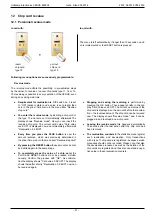
8.2 Mounting notes
●
This device may only be mounted on a suitable surface.
● The device must be sufficiently secured, take into consi-
deration the weight of the inserted coins. There are 3 holes
in the back of the casing to accomplish the mounting pro-
cess. Screws and dowels are included by delivery.
●
The device must be mounted horizontally and vertically to
guarantee a flawless function of the coin receiver. That
means the angle of the device can only be maximum 2 º,
sloping forward or backward, as well as to the right or the
left.
●
The device must be mounted perpendicular and horizontally,
to avouch a faultless function of the coin acceptance.
That implies, the tilt angle of the device can only be maxi-
mal 2° forwards or backwards and maximal 2° to the right or
left.
● The input cables are fixed by three drilled holes in the rear
wall. The device is corresponding to protection type IP 20
and may only be used in dry rooms. Choose a cable cross
section of the feed line adequate big. Attend thereby the
connected electrical load. Attend to the VDE guidelines.
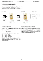
8.3 Montageanleitung
● Switch off the power supply by switching over the corres-
ponding isolating switch, the fuse or even by tripping the
RCCB.
●
Unlock the lock on the front panel and remove it to the
extent, that it is possible to remove the electrical connec-
tors.
●
The device horizontal and vertically align with the help of
a level.
The tilt angle can only be 2° now mark the drilled holes.
●
Drill the holes and insert suitable dowels. Make the
electrical connection through the holes in the bottom
of the housing. Then fix the housing with suitable screws.
Now restore the electrical connections to the front panel.
Fit the front panel and lock with the lock.
8 Installation
8.1 Installation notes
Through high quality micro-electronics is the device able to re-
ach a high standard of reliability in the daily use. Only if the in-
stallation has been professionally carried out can the device be
guaranteed.
Please consider during the installation...
● Only authorized and qualified electricians carry out the ins-
tallation complying with the valid VDE–regulations.
● By the timers with 230 V~ supply voltage is definitely the
protection cable required, by the timers 24 V~ (safety ex-
tra-low voltage) protecting grounding is needed as function
earth.
● That the floor covering is anti-static and conductor capable,
to ensure a minimum of static change and so reducing
the danger to the electronics.
●
A malfunction or breakdown of the device can be caused
by the switching sparks of the relay contacts. To reduce
these sparks appropriate suppression combinations must
be included parallel to the protection contacts. RC combi-
nations for sparks reducing are only affective by direct par-
allel switching of the relay contacts.
●
That the screened control and data cable are laid separa-
tely from mains cables. The screening of the VENUS electro-
nic must be one - side and laid on PE.
●
That the feed line are used, which is from a big cross section
to supply both the VENUS and the attached electric con-
sumer. It should be used an cross section from 1,5 mm² at
the minimum.
Summary of Contents for VENUS 6600 XL
Page 1: ...Operating instruction VENUS 6600 XL Chip card system ...
Page 28: ...Holtkamp Electronics VENUS 6600XL techn Stand 04 2016 4074_04 2016 V09 2019 28 ...
Page 30: ...Holtkamp Electronics VENUS 6600XL techn Stand 04 2016 4074_04 2016 V09 2019 30 ...
Page 31: ...Holtkamp Electronics VENUS 6600XL techn Stand 04 2016 4074_04 2016 V09 2019 31 ...


