background image

Rev. 1.60

142

August 20, 2019

Rev. 1.60

143

August 20, 2019

BS66F340/BS66F350/BS66F360/BS66F370

Touch A/D Flash MCU with LED Driver

BS66F340/BS66F350/BS66F360/BS66F370

Touch A/D Flash MCU with LED Driver

Counter Value

CCRP

CCRA

PTON

PTPAU

PTPOL

CCRP Int. 

Flag PTMPF

CCRA Int. 

Flag PTMAF

PTM O/P Pin

(

PTOC=1

)

Time

Counter stopped 

by CCRA

Pause

Resume

Counter Stops 

by software

Counter Reset when 

PTON returns high

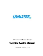
PTM [1:0] = 10 ; PTIO [1:0] = 11 

Pulse Width 

set by CCRA

Output Inverts

when PTPOL = 1

No CCRP Interrupts 

generated

PTM O/P Pin

(

PTOC=0

)

PTCK pin

Software 

Trigger

Cleared by 

CCRA match

PTCK pin 

Trigger

Auto. set by 

PTCK pin

Software 

Trigger

Software 

Clear

Software 

Trigger

Software 

Trigger

Single Pulse Mode

Note: 1. Counter stopped by CCRA

2. CCRP is not used

3. The pulse triggered by the PTCK pin or by setting the PTON bit high

4. A PTCK pin active edge will automatically set the PTON bit high.

5. In the Single Pulse Mode, PTIO [1:0] must be set to "11" and can not be changed.

Summary of Contents for BS66F340

Page 1: ...Touch A D Flash MCU with LED Driver BS66F340 BS66F350 BS66F360 BS66F370 Revision V1 60 Date August 20 2019 ...

Page 2: ...cteristics 32 Touch Key Electrical Characteristics 32 Power on Reset Characteristics 34 System Architecture 35 Clocking and Pipelining 35 Program Counter 36 Stack 37 Arithmetic and Logic Unit ALU 37 Flash Program Memory 38 Structure 38 Special Vectors 38 Look up Table 39 Table Program Example 39 In Circuit Programming ICP 40 On Chip Debug Support OCDS 41 In Application Programming IAP 41 Data Memo...

Page 3: ... External Crystal Ceramic Oscillator HXT 68 Internal High Speed RC Oscillator HIRC 69 External 32 768 kHz Crystal Oscillator LXT 69 Internal 32kHz Oscillator LIRC 70 Operating Modes and System Clocks 70 System Clocks 70 System Operation Modes 71 Control Registers 72 Operating Mode Switching 75 Standby Current Considerations 79 Wake up 79 Watchdog Timer 80 Watchdog Timer Clock Source 80 Watchdog Ti...

Page 4: ...132 Periodic TM Operation 132 Periodic Type TM Register Description 133 Periodic Type TM Operation Modes 136 Analog to Digital Converter 145 A D Converter Overview 145 Registers Descriptions 146 A D Converter Operation 150 A D Converter Reference Voltage 151 A D Converter Input Pins 152 Conversion Rate and Timing Diagram 152 Summary of A D Conversion Steps 153 Programming Considerations 153 A D Co...

Page 5: ...ch Key Interrupt 209 UART Transfer Interrupt 209 A D Converter Interrupt 209 Multi function Interrupt 209 Time Base Interrupt 210 Serial Interface Module Interrupt 211 LVD Interrupt 212 EEPROM Interrupt 212 TM Interrupt 212 Programming Considerations 213 Application Circuits 214 Instruction Set 215 Introduction 215 Instruction Timing 215 Moving and Transferring Data 215 Arithmetic Operations 215 L...

Page 6: ...60 BS66F370 Touch A D Flash MCU with LED Driver Package Information 237 28 pin SSOP 150mil Outline Dimensions 238 44 pin LQFP 10mm 10mm FP2 0mm Outline Dimensions 239 48 pin LQFP 7mm 7mm Outline Dimensions 240 64 pin LQFP 7mm 7mm Outline Dimensions 241 ...

Page 7: ... 32K 16 Data Memory Up to 1536 8 True EEPROM Memory 128 8 Fully integrated touch key functions require no external components Watchdog Timer function Up to 60 bidirectional I O lines Two external interrupt lines shared with I O pins Multiple Timer Modules for time measure input capture compare match output PWM output function or single pulse output function Serial Interfaces Module SIM for SPI or ...

Page 8: ...operating modes using different clock sources gives users the ability to optimise microcontroller operation and minimise power consumption Easy communication with the outside world is provided using the internal UART I2 C and SPI interfaces while the inclusion of flexible I O programming features Timer modules and many other features further enhance device functionality and flexibility The touch k...

Page 9: ... UART Internal HIRC LIRC Oscillators Temperature Sensor Touch Key Modules External LXT Oscillator Pin Assignment 28 27 26 25 24 23 22 21 20 19 18 17 16 15 1 2 3 4 5 6 7 8 9 10 11 12 13 14 PE4 OSC1 PE5 CTP1B OSC2 PB7 INT1 KEY4 AN7 PB6 PTCK KEY3 AN6 PB5 STCK KEY2 AN5 PB4 PTPI PTPB KEY1 AN4 PA4 SDO XT2 VSS VDD PB0 SDI SDA VREF AN0 PB1 SCK SCL AN1 PB2 PTPI TX PTP AN2 PA3 SCS XT1 PB3 RX AN3 PC0 KEY5 PC...

Page 10: ...TPI STPB PE2 STPI STP PA2 SCS ICPCK OCDSCK NC NC NC NC NC PE0 PD7 KEY20 PC7 KEY12 PC6 KEY11 PC5 KEY10 PC4 KEY9 PC3 KEY8 PC2 KEY7 BS66F350 BS66V350 48 LQFP A 1 2 3 4 5 6 7 8 9 10 11 12 13 14 15 16 17 18 19 20 21 22 23 24 25 26 27 28 29 30 31 32 33 34 35 36 45 46 47 48 37 38 39 40 41 42 43 44 PE5 CTCK1 OSC2 PE4 OSC1 PE7 CTP1B PE6 CTP1 PA1 CTP0 PA5 CTP0B PA6 CTCK0 INT0 PA7 PD3 KEY16 PD2 KEY15 PD1 KEY...

Page 11: ...A2 SCS ICPCK OCDSCK PF5 PF3 PF2 PF1 KEY28 PF0 KEY27 PE0 PD7 KEY20 PC7 KEY12 PC6 KEY11 PC5 KEY10 PC4 KEY9 PC3 KEY8 PC2 KEY7 BS66F360 BS66V360 48 LQFP A 1 2 3 4 5 6 7 8 9 10 11 12 13 14 15 16 17 18 19 20 21 22 23 24 25 26 27 28 29 30 31 32 33 34 35 36 45 46 47 48 37 38 39 40 41 42 43 44 PE5 CTCK1 OSC2 PE4 OSC1 PE7 CTP1B KEY26 PE6 CTP1 KEY25 PA1 CTP0 PA5 CTP0B PA6 CTCK0 INT0 PA7 PD3 KEY16 PD2 KEY15 P...

Page 12: ...PF0 KEY27 PE0 KEY21 PD7 KEY20 PC7 KEY12 PC6 KEY11 PC5 KEY10 PC4 KEY9 PC3 KEY8 PC2 KEY7 PA0 SDO ICPDA OCDSDA PA2 SCS ICPCK OCDSCK BS66F370 BS66V370 48 LQFP A 1 2 3 4 5 6 7 8 9 10 11 12 13 14 15 16 17 18 19 20 21 22 23 24 25 26 27 28 29 30 31 32 33 34 35 36 45 46 47 48 37 38 39 40 41 42 43 44 PE5 CTCK1 OSC2 PE4 OSC1 PE7 CTP1B KEY26 PE6 CTP1 KEY25 PA1 CTP0 PA5 CTP0B PA6 CTCK0 INT0 PA7 PD3 KEY16 PD2 K...

Page 13: ...S VDD PE5 CTCK1 OSC2 PE4 OSC1 PB3 RX AN3 PB2 PTP PTPI TX AN2 PB0 VREF SDI SDA AN0 PB1 SCK SCL AN1 VSS1 VDD1 PC3 KEY8 PC2 KEY7 PC1 KEY6 PC0 KEY5 PC7 KEY12 PC6 KEY11 PC5 KEY10 PC4 KEY9 PB4 PTPB PTPI AN4 KEY1 PB5 STCK AN5 KEY2 PB7 INT1 AN7 KEY4 PB6 PTCK AN6 KEY3 PE3 STPB STPI KEY24 PE2 STP STPI KEY23 PF1 KEY28 PF0 KEY27 PE7 CTP1B KEY26 PE6 CTP1 KEY25 PD3 KEY16 PD2 KEY15 PD1 KEY14 PD0 KEY13 Note 1 The...

Page 14: ...SDO PAS0 CMOS SPI data output ICPDA ST CMOS ICP Data Address pin OCDSDA ST CMOS OCDS Data Address pin for EV chip only PA1 CTP0 PA1 PAWU PAPU PAS0 ST CMOS General purpose I O Register enabled pull up and wake up CTP0 PAS0 CMOS CTM0 output PA2 CTCK1 SCS ICPCK OCDSCK PA2 PAWU PAPU PAS0 ST CMOS General purpose I O Register enabled pull up and wake up CTCK1 PAS0 ST CTM1 clock input SCS PAS0 IFS ST CMO...

Page 15: ...TX serial data output PTP PBS0 CMOS PTM output AN2 PBS0 AN A D Converter analog input PB3 RX AN3 PB3 PBPU PBS0 ST CMOS General purpose I O Register enabled pull up RX PBS0 ST UART RX serial data input AN3 PBS0 AN A D Converter analog input PB4 PTPI PTPB KEY1 AN4 PB4 PBPU PBS1 ST CMOS General purpose I O Register enabled pull up PTPI PBS1 IFS ST PTM capture input PTPB PBS1 CMOS PTM inverted output ...

Page 16: ...ES0 AN Touch key input PE2 STPI STP KEY11 PE2 PEPU PES0 ST CMOS General purpose I O Register enabled pull up STPI PES0 IFS ST STM capture input STP PES0 CMOS STM output KEY11 PES0 AN Touch key input PE3 STPI STPB KEY12 PE3 PEPU PES0 ST CMOS General purpose I O Register enabled pull up STPI PES0 IFS ST STM capture input STPB PES0 CMOS STM inverted output KEY12 PES0 AN Touch key input PE4 OSC1 PE4 P...

Page 17: ...U PAS0 ST CMOS General purpose I O Register enabled pull up and wake up SCS PAS0 IFS ST CMOS SPI slave select XT1 PAS0 LXT LXT oscillator pin PA4 SDO XT2 PA4 PAWU PAPU PAS1 ST CMOS General purpose I O Register enabled pull up and wake up SDO PAS1 CMOS SPI data output XT2 PAS1 LXT LXT oscillator pin PA5 CTP0B PA5 PAWU PAPU PAS1 ST CMOS General purpose I O Register enabled pull up and wake up CTP0B ...

Page 18: ...ted output KEY1 PBS1 AN Touch key input AN4 PBS1 AN A D Converter analog input PB5 STCK KEY2 AN5 PB5 PBPU PBS1 ST CMOS General purpose I O Register enabled pull up STCK PBS1 ST STM clock input KEY2 PBS1 AN Touch key input AN5 PBS1 AN A D Converter analog input PB6 PTCK KEY3 AN6 PB6 PBPU PBS1 ST CMOS General purpose I O Register enabled pull up PTCK PBS1 ST PTM clock input KEY3 PBS1 AN Touch key in...

Page 19: ... input PD3 KEY16 PD3 PDPU PDS0 ST CMOS General purpose I O Register enabled pull up KEY16 PDS0 AN Touch key input PD4 KEY17 PD4 PDPU PDS1 ST CMOS General purpose I O Register enabled pull up KEY17 PDS1 AN Touch key input PD5 KEY18 PD5 PDPU PDS1 ST CMOS General purpose I O Register enabled pull up KEY18 PDS1 AN Touch key input PD6 KEY19 PD6 PDPU PDS1 ST CMOS General purpose I O Register enabled pul...

Page 20: ...n OPT I T O T Description PA0 SDO ICPDA OCDSDA PA0 PAWU PAPU PAS0 ST CMOS General purpose I O Register enabled pull up and wake up SDO PAS0 CMOS SPI data output ICPDA ST CMOS ICP Data Address pin OCDSDA ST CMOS OCDS Data Address pin for EV chip only PA1 CTP0 PA1 PAWU PAPU PAS0 ST CMOS General purpose I O Register enabled pull up and wake up CTP0 PAS0 CMOS CTM0 output PA2 SCS ICPCK OCDSCK PA2 PAWU ...

Page 21: ... AN A D Converter analog input PB2 PTPI TX PTP AN2 PB2 PBPU PBS0 ST CMOS General purpose I O Register enabled pull up PTPI PBS0 IFS ST PTM capture input TX PBS0 CMOS UART TX serial data output PTP PBS0 CMOS PTM output AN2 PBS0 AN A D Converter analog input PB3 RX AN3 PB3 PBPU PBS0 ST CMOS General purpose I O Register enabled pull up RX PBS0 ST UART RX serial data input AN3 PBS0 AN A D Converter an...

Page 22: ...C5 KEY10 PC5 PCPU PCS1 ST CMOS General purpose I O Register enabled pull up KEY10 PCS1 AN Touch key input PC6 KEY11 PC6 PCPU PCS1 ST CMOS General purpose I O Register enabled pull up KEY11 PCS1 AN Touch key input PC7 KEY12 PC7 PCPU PCS1 ST CMOS General purpose I O Register enabled pull up KEY12 PCS1 AN Touch key input PD0 KEY13 PD0 PDPU PDS0 ST CMOS General purpose I O Register enabled pull up KEY...

Page 23: ...gister enabled pull up OSC1 PES1 HXT HXT oscillator pin PE5 CTCK1 OSC2 PE5 PEPU PES1 ST CMOS General purpose I O Register enabled pull up CTCK1 PES1 ST CTM1 clock input OSC2 PES1 HXT HXT oscillator pin PE6 CTP1 KEY25 PE6 PEPU PES1 ST CMOS General purpose I O Register enabled pull up CTP1 PES1 CMOS CTM1 output KEY25 PES1 AN Touch key input PE7 CTP1B KEY26 PE7 PEPU PES1 ST CMOS General purpose I O R...

Page 24: ... SPI slave select XT1 PAS0 LXT LXT oscillator pin PA4 SDO XT2 PA4 PAWU PAPU PAS1 ST CMOS General purpose I O Register enabled pull up and wake up SDO PAS1 CMOS SPI data output XT2 PAS1 LXT LXT oscillator pin PA5 CTP0B PA5 PAWU PAPU PAS1 ST CMOS General purpose I O Register enabled pull up and wake up CTP0B PAS1 CMOS CTM0 inverted output PA6 CTCK0 INT0 PA6 PAWU PAPU PAS1 ST CMOS General purpose I O...

Page 25: ... enabled pull up STCK PBS1 ST STM clock input KEY2 PBS1 AN Touch key input AN5 PBS1 AN A D Converter analog input PB6 PTCK KEY3 AN6 PB6 PBPU PBS1 ST CMOS General purpose I O Register enabled pull up PTCK PBS1 ST PTM clock input KEY3 PBS1 AN Touch key input AN6 PBS1 AN A D Converter analog input PB7 INT1 KEY4 AN7 PB7 PBPU PBS1 ST CMOS General purpose I O Register enabled pull up INT1 PBS1 INTEG INT...

Page 26: ...abled pull up KEY16 PDS0 AN Touch key input PD4 KEY17 PD4 PDPU PDS1 ST CMOS General purpose I O Register enabled pull up KEY17 PDS1 AN Touch key input PD5 KEY18 PD5 PDPU PDS1 ST CMOS General purpose I O Register enabled pull up KEY18 PDS1 AN Touch key input PD6 KEY19 PD6 PDPU PDS1 ST CMOS General purpose I O Register enabled pull up KEY19 PDS1 AN Touch key input PD7 KEY20 PD7 PDPU PDS1 ST CMOS Gen...

Page 27: ...FPU ST CMOS General purpose I O Register enabled pull up PF4 PF4 PFPU ST CMOS General purpose I O Register enabled pull up PF5 PF5 PFPU ST CMOS General purpose I O Register enabled pull up PG0 KEY29 PG0 PGPU PGS0 ST CMOS General purpose I O Register enabled pull up KEY29 PGS0 AN Touch key input PG1 KEY30 PG1 PGPU PGS0 ST CMOS General purpose I O Register enabled pull up KEY30 PGS0 AN Touch key inp...

Page 28: ... Storage Temperature 50 C to 125 C Operating Temperature 40 C to 85 C IOH Total 80mA IOL Total 80mA Total Power Dissipation 500mW Note These are stress ratings only Stresses exceeding the range specified under Absolute Maximum Ratings may cause substantial damage to the device Functional operation of this device at other conditions beyond those listed in the specification is not implied and prolon...

Page 29: ...nt SLEEP Mode 3V fSYS off fSUB off No load all peripherals off WDT enabled 1 2 1 8 μA 5V 1 8 2 7 μA VIL Input Low Voltage for I O Ports or Input Pins 5V 0 0 1 5 V 0 0 0 2VDD V VIH Input High Voltage for I O Ports or Input Pins 5V 3 5 5 0 V 0 8VDD VDD V IOL Sink Current for I O Pins 3V VOL 0 1VDD 17 34 mA 5V 34 68 mA IOH Source Current for I O Pins 3V VOH 0 9VDD 5 5 11 0 mA 5V 11 22 mA Programming ...

Page 30: ... 5V Ta 40 C 85 C 10 12 10 MHz 5V Ta 25 C 20 8 20 MHz 5V Ta 25 C 20 16 20 MHz fLIRC Low Speed Internal RC Oscillator LIRC 5V Ta 25 C 10 32 10 kHz 2 2V 5 5V Ta 40 C 85 C 40 32 40 kHz tTPI STPI PTPI pin Minimum Input Pulse Width 0 3 μs tTCK CTCKn STCK PTCK pin Minimum Input Pulse Width 0 3 μs tINT Interrupt Pin Minimum Input Pulse Width 10 μs tSST System Start up Timer Period Wake up from Power Down ...

Page 31: ... Temperature sensor output 1 0 2 0 μs tADC Conversion Time Including A D Sample and Hold Time AN Temperature sensor output 16 tADCK AN Temperature sensor output 56 tADCK tON2ST A D Converter On to Start Time 4 μs Temperature Sensor Electrical Characteristics Ta 25 C Operating Temperature 40 C 85 C unless otherwise specified Symbol Parameter Test Conditions Min Typ Max Unit VDD Conditions VDD Opera...

Page 32: ... on 150 μs tLVR Minimum Low Voltage Width to Reset 120 240 480 μs tLVD Minimum Low Voltage Width to Interrupt 60 120 240 μs Touch Key Electrical Characteristics Ta 25 C Touch Key RC Oscillator 500kHz Mode Selected Symbol Parameter Test Conditions Min Typ Max Unit VDD Conditions IKEYOSC Only Sensor KEY Oscillator Operating Current 3V fSENOSC 500kHz 30 60 µA 5V 60 120 IREFOSC Only Reference Oscillat...

Page 33: ...to 1000kHz 2 fREFOSC 1000kHz Adjust Reference oscillator internal capacitor to make sure that the reference oscillator frequency is equal to 1000kHz Touch Key RC Oscillator 1500kHz Mode Selected Symbol Parameter Test Conditions Min Typ Max Unit VDD Conditions IKEYOSC Only Sensor KEY Oscillator Operating Current 3V fSENOSC 1500kHz 60 120 µA 5V 120 240 IREFOSC Only Reference Oscillator Operating Cur...

Page 34: ...kHz 4 8 20 pF 5V 5 10 20 pF fKEYOSC Sensor KEY Oscillator Operating Frequency 3V CEXT 3 4 5 6 7 8 9 50pF 150 2000 4000 kHz 5V 150 2000 4000 kHz fREFOSC Reference Oscillator Operating Frequency 3V CEXT 3 4 5 6 7 8 9 50pF 150 2000 4000 kHz 5V 150 2000 4000 kHz Note 1 fSENOSC 2000kHz Adjust KEYn external capacitor to make sure that the Sensor oscillator frequency is equal to 2000kHz 2 fREFOSC 2000kHz...

Page 35: ...imum reliability and flexibility This makes these devices suitable for low cost high volume production for controller applications Clocking and Pipelining The main system clock derived from either a HXT LXT HIRC or LIRC oscillator is subdivided into four internally generated non overlapping clocks T1 T4 The Program Counter is incremented at the beginning of the T1 clock during which time a new ins...

Page 36: ...icrocontroller manages program control by loading the required address into the Program Counter For conditional skip instructions once the condition has been met the next instruction which has already been fetched during the present instruction execution is discarded and a dummy cycle takes its place while the correct instruction is obtained Device Program Counter High Byte Low Byte PCL BS66F340 P...

Page 37: ...recautions should be taken to avoid such cases which might cause unpredictable program branching If the stack is overflow the first Program Counter save in the stack will be lost Stack Pointer Stack Level 2 Stack Level 1 Stack Level 3 Stack Level N Program Memory Program Counter Bottom of Stack Top of Stack Note N 8 for BS66F340 BS66F350 N 12 for BS66F360 while N 16 for BS66F370 Arithmetic and Log...

Page 38: ...K 16 to 32K 16 bits The Program Memory is addressed by the Program Counter and also contains data table information and interrupt entries Table data which can be setup in any location within the Program Memory is addressed by a separate table pointer registers 000H Initialisation Vector 004H FFFH 16 bits Interrupt Vectors Look up Table n00H nFFH BS66F340 Initialisation Vector 16 bits Interrupt Vec...

Page 39: ... t e r Table Program Example The accompanying example shows how the table pointer and table data is defined and retrieved from the device This example uses raw table data located in the last page which is stored there using the ORG statement The value at this ORG statement is 0F00H which refers to the start address of the last page within the 4K Program Memory of the BS66F340 device The table poin...

Page 40: ...As an additional convenience Holtek has provided a means of programming the microcontroller in circuit using a 4 pin interface This provides manufacturers with the possibility of manufacturing their circuit boards complete with a programmed or un programmed microcontroller and then programming or upgrading the program at a later stage This enables product manufacturers to easily keep their manufac...

Page 41: ...V chip device for debugging the corresponding pin functions shared with the OCDSDA and OCDSCK pins in the real MCU device will have no effect in the EV chip However the two OCDS pins which are pin shared with the ICP programming pins are still used as the Flash Memory programming pins for ICP For more detailed OCDS information refer to the corresponding document named Holtek e Link for 8 bit MCU O...

Page 42: ...FRD FC1 D7 D6 D5 D4 D3 D2 D1 D0 FC2 BS66F350 360 370 CLWB FARL A7 A6 A5 A4 A3 A2 A1 A0 FARH BS66F340 A11 A10 A9 A8 FARH BS66F350 A12 A11 A10 A9 A8 FARH BS66F360 A13 A12 A11 A10 A9 A8 FARH BS66F370 A14 A13 A12 A11 A10 A9 A8 FD0L D7 D6 D5 D4 D3 D2 D1 D0 FD0H D15 D14 D13 D12 D11 D10 D9 D8 FD1L D7 D6 D5 D4 D3 D2 D1 D0 FD1H D15 D14 D13 D12 D11 D10 D9 D8 FD2L D7 D6 D5 D4 D3 D2 D1 D0 FD2H D15 D14 D13 D12...

Page 43: ... write process This bit is set by software and cleared by hardware when the Flash memory write process is completed Bit 1 FRDEN Flash memory Read Enable control 0 Flash memory read disable 1 Flash memory read enable Bit 0 FRD Flash memory Read Initiate control 0 Do not initiate Flash memory read or Flash memory read process is completed 1 Initiate Flash memory read process This bit is set by softw...

Page 44: ...2 A11 A10 A9 A8 R W R W R W R W R W R W POR 0 0 0 0 0 Bit 7 5 Unimplemented read as 0 Bit 4 0 Flash Memory Address bit 12 bit 8 FARH Register BS66F360 Bit 7 6 5 4 3 2 1 0 Name A13 A12 A11 A10 A9 A8 R W R W R W R W R W R W R W POR 0 0 0 0 0 0 Bit 7 6 Unimplemented read as 0 Bit 5 0 Flash Memory Address bit 13 bit 8 FARH Register BS66F370 Bit 7 6 5 4 3 2 1 0 Name A14 A13 A12 A11 A10 A9 A8 R W R W R ...

Page 45: ... 0 0 0 0 0 0 0 0 Bit 7 0 The second Flash Memory data bit 15 bit 8 FD2L Register Bit 7 6 5 4 3 2 1 0 Name D7 D6 D5 D4 D3 D2 D1 D0 R W R W R W R W R W R W R W R W R W POR 0 0 0 0 0 0 0 0 Bit 7 0 The third Flash Memory data bit 7 bit 0 FD2H Register Bit 7 6 5 4 3 2 1 0 Name D15 D14 D13 D12 D11 D10 D9 D8 R W R W R W R W R W R W R W R W R W POR 0 0 0 0 0 0 0 0 Bit 7 0 The third Flash Memory data bit 1...

Page 46: ...ncorrect the Flash memory write operation will not be enabled and users must again repeat the above procedure Then the FWPEN bit will automatically be cleared to 0 by hardware 6 If the pattern data is correct before the counter overflows the Flash memory write operation will be enabled and the FWPEN bit will automatically be cleared to 0 by hardware The CFWEN bit will also be set to 1 by hardware ...

Page 47: ...e content of FARL 7 5 and FARL 7 6 bit field respectively Erase Block FARH 3 0 FARL 7 0 0 0000 x x x x x x x x 1 0001 x x x x x x x x 2 0010 x x x x x x x x 3 0011 x x x x x x x x 4 0100 x x x x x x x x 5 0101 x x x x x x x x 6 0110 x x x x x x x x 7 0111 x x x x x x x x 8 1000 x x x x x x x x 9 1001 x x x x x x x x 10 1010 x x x x x x x x 11 1011 x x x x x x x x 12 1100 x x x x x x x x 13 1101 x ...

Page 48: ... 0011 1111 10 xx xxxx 255 0011 1111 11 xx xxxx x don t care BS66F360 Erase Page Number and Selection Erase Page FARH FARL 7 6 FARL 5 0 0 0000 0000 00 xx xxxx 1 0000 0000 01 xx xxxx 2 0000 0000 10 xx xxxx 3 0000 0000 11 xx xxxx 4 0000 0001 00 xx xxxx 5 0000 0001 01 xx xxxx 126 0001 1111 10 xx xxxx 127 0001 1111 11 xx xxxx 128 0010 0000 00 xx xxxx 129 0010 0000 01 xx xxxx 254 0011 1111 10 xx xxxx 25...

Page 49: ...S66F370 Touch A D Flash MCU with LED Driver Read Flash Memory Clear FRDEN bit END Read Finish Yes No Set FMOD 2 0 011 FRDEN 1 Set Flash Address registers FARH xxh FARL xxh FRD 0 Yes No Read data value FD0L xxh FD0H xxh Set FRD 1 Read Flash Memory Procedure ...

Page 50: ... Set FWT 1 FWT 0 Yes No Set Block Erase address FARH FARL Set FMOD 2 0 001 FWT 1 Select Block Erase mode Initiate write operation FWT 0 Yes No END Write Finish Yes No Clear CFWEN 0 Set FMOD 2 0 000 Select Write Flash Mode Set Write starting address FARH FARL Write data to data register FD0L FD0H FD1L FD1H FD2L FD2H FD3L FD3H Write Flash Memory Procedure BS66F340 ...

Page 51: ... address FARH FARL Set FMOD 2 0 001 FWT 1 Select Page Erase mode Initiate write operation FWT 0 Yes No END Write Finish Yes No Clear CFWEN 0 Set FMOD 2 0 000 Select Write Flash Mode Set Write starting address FARH FARL Write data to data register FD0L FD0H Page data Write finish Yes No Write Flash Memory Procedure BS66F350 BS66F360 BS66F370 Note When the FWT or FRD bit is set to 1 the MCU is stopp...

Page 52: ...rs to correct value Structure The Data Memory is subdivided into several sectors all of which are implemented in 8 bit wide Memory Each of the Data Memory sectors is categorized into two types the Special Purpose Data Memory and the General Purpose Data Memory The address range of the Special Purpose Data Memory for the device is from 00H to 7FH The General Purpose Data Memory address range is fro...

Page 53: ...he indirect addressing access The main difference between standard instructions and extended instructions is that the data memory address m in the extended instructions can be from 10 bits to 11 bits depending upon which device is selected the high byte indicates a sector and the low byte indicates a specific address General Purpose Data Memory All microcontroller programs require an area of read ...

Page 54: ...6FH 70H 30H 31H 32H 38H 3CH 33H 34H 35H 36H 37H 3BH 39H 3AH 71H 72H 73H 74H 75H 76H 7BH PBC PBPU PB 3DH 3FH 3EH 7FH MP1H IAR2 MP2L MP2H PSCR0 TB1C SCC HXTC LXTC RSTC PCC PCPU PC 57H 58H 59H 5AH 5BH 5CH 5DH 5EH 5FH SIMTOC SIMC0 SIMC1 SIMD SIMA SIMC2 FC0 FC1 FARL FARH FD0L FD0H FD1L FD1H FD2L FD2H FD3L FD3H Sector 1 HIRCC RSTFC INTC1 INTC2 ADRL ADCR0 ADRH ADCR1 PSCR1 SLEDC PTMC0 PTMC1 PTMDL PTMDH PT...

Page 55: ...H 74H 75H 76H 7BH PBC PBPU PB 3DH 3FH 3EH 7FH MP1H IAR2 MP2L MP2H PSCR0 TB1C SCC HXTC LXTC RSTC PCC PCPU PC 57H 58H 59H 5AH 5BH 5CH 5DH 5EH 5FH SIMTOC SIMC0 SIMC1 SIMD SIMA SIMC2 FC0 FC1 FARL FARH FD0L FD0H FD1L FD1H FD2L FD2H FD3L FD3H Sector 1 HIRCC RSTFC INTC1 INTC2 PD PDC PDPU ADRL ADCR0 ADRH ADCR1 PSCR1 SLDEC PTMC0 PTMC1 PTMDL PTMDH PTMAL PTMAH PTMRPL PTMRPH STMC0 STMC1 STMDL STMDH STMAL STMA...

Page 56: ...0 TB1C SCC HXTC LXTC RSTC PCC PCPU PC 57H 58H 59H 5AH 5BH 5CH 5DH 5EH 5FH SIMTOC SIMC0 SIMC1 SIMD SIMA SIMC2 FC0 FC1 FARL FARH FD0L FD0H FD1L FD1H FD2L FD2H FD3L FD3H Sector 1 HIRCC RSTFC INTC1 INTC2 PD PDC PDPU ADRL ADCR0 ADRH ADCR1 PSCR1 SLEDC PTMC0 PTMC1 PTMDL PTMDH PTMAL PTMAH PTMRPL PTMRPH STMC0 STMC1 STMDL STMDH STMAL STMAH STMRP CTM1C0 CTM1C1 CTM1DL CTM1DH CTM1AL CTM1AH TSC0 TSC1 TSC2 TSC3 ...

Page 57: ...MA SIMC2 FC0 FC1 FARL FARH FD0L FD0H FD1L FD1H FD2L FD2H FD3L FD3H Sector 1 HIRCC RSTFC INTC1 INTC2 PD PDC PDPU ADRL ADCR0 ADRH ADCR1 PSCR1 SLEDC PTMC0 PTMC1 PTMDL PTMDH PTMAL PTMAH PTMRPL PTMRPH STMC0 STMC1 STMDL STMDH STMAL STMAH STMRP CTM1C0 CTM1C1 CTM1DL CTM1DH CTM1AL CTM1AH TSC0 TSC1 TSC2 TSC3 PE PEC PEPU 77H 78H USR UCR1 UCR2 TXR_RXR BRG 79H 7AH TKTMR TKC0 TK16DL TK16DH TKC1 TKM016DL TKM016D...

Page 58: ...sing Registers indirectly will return a result of 00H and writing to the registers indirectly will result in no operation Memory Pointers MP0 MP1H MP1L MP2H MP2L Five Memory Pointers known as MP0 MP1L MP1H MP2L and MP2H are provided These Memory Pointers are physically implemented in the Data Memory and can be manipulated in the same way as normal registers providing a convenient way with which to...

Page 59: ... inc mp1l increment memory pointer MP1L sdz block check if last memory location has been cleared jmp loop continue The important point to note here is that in the example shown above no reference is made to specific RAM addresses Direct Addressing Program Example using extended instructions data section data temp db code section at 0 code org 00h start lmov a m move m data to acc lsub a m 1 compar...

Page 60: ...umulator ACC The Accumulator is central to the operation of any microcontroller and is closely related with operations carried out by the ALU The Accumulator is the place where all intermediate results from the ALU are stored Without the Accumulator it would be necessary to write the result of each calculation or logical operation such as addition subtraction shift etc to the Data Memory resulting...

Page 61: ... up a WDT time out or by executing the CLR WDT or HALT instruction The PDF flag is affected only by executing the HALT or CLR WDT instruction or during a system power up The Z OV AC C SC and CZ flags generally reflect the status of the latest operations C is set if an operation results in a carry during an addition operation or if a borrow does not take place during a subtraction operation otherwi...

Page 62: ...g Time out flag 0 After power up ow executing the CLR WDT or HALT instruction 1 A watchdog time out occurred Bit 4 PDF Power down flag 0 After power up ow executing the CLR WDT instruction 1 By executing the HALT instructin Bit 3 OV Overflow flag 0 No overflow 1 An operation results in a carry into the highest order bit but not a carry out of the highest order bit or vice versa Bit 2 Z Zero flag 0...

Page 63: ...the same way as the other types of memory Read and Write operations to the EEPROM are carried out in single byte operations using an address and data register in sector 0 and a single control register in sector 1 EEPROM Registers Three registers control the overall operation of the internal EEPROM Data Memory These are the address register EEA the data register EED and a single control register EE...

Page 64: ... application program will activate a write cycle This bit will be automatically reset to zero by the hardware after the write cycle has finished Setting this bit high will have no effect if the WREN has not first been set high Bit 1 RDEN Data EEPROM read enable 0 Disable 1 Enable This is the Data EEPROM Read Enable Bit which must be set high before Data EEPROM read operations are carried out Clear...

Page 65: ...ill have been written into the EEPROM Detecting when the write cycle has finished can be implemented either by polling the WR bit in the EEC register or by using the EEPROM interrupt When the write cycle terminates the WR bit will be automatically cleared to zero by the microcontroller informing the user that the data has been written to the EEPROM The application program can therefore poll the WR...

Page 66: ...he device should not enter the IDLE or SLEEP mode until the EEPROM read or write operation is totally complete Otherwise the EEPROM read or write operation will fail Programming Example Reading data from the EEPROM polling method MOV A EEPROM_ADRES user defined address MOV EEA A MOV A 040H setup memory pointer low byte MP1L MOV MP1L A MP1L points to EEC register MOV A 01H setup Memory Pointer high...

Page 67: ...ize the performance power ratio a feature especially important in power sensitive portable applications Type Name Frequency Pins External High Speed Crystal HXT 400 kHz 20 MHz OSC1 OSC2 Internal High Speed RC HIRC 8 12 16 MHz External Low Speed Crystal LXT 32 768 kHz XT1 XT2 Internal Low Speed RC LIRC 32 kHz Oscillator Types System Clock Configurations There are four methods of generating the syst...

Page 68: ...nal capacitors However for some crystal types and frequencies to ensure oscillation it may be necessary to add two small value capacitors C1 and C2 Using a ceramic resonator will usually require two small value capacitors C1 and C2 to be connected as shown for oscillation to occur The values of C1 and C2 should be selected in consultation with the crystal or resonator manufacturer s specification ...

Page 69: ...ide frequency compensation due to different crystal manufacturing tolerances After the LXT oscillator is enabled by setting the LXTEN bit to 1 there is a time delay associated with the LXT oscillator waiting for it to start up When the microcontroller enters the SLEEP or IDLE Mode the system clock is switched off to stop microcontroller activity and to conserve power However in many microcontrolle...

Page 70: ...on circuits are used to ensure that the influence of the power supply voltage temperature and process variations on the oscillation frequency are minimised As a result at a power supply of 5V and at a temperature of 25 C degrees the fixed oscillation frequency of 32 kHz will have a tolerance within 10 Operating Modes and System Clocks Present day applications require that their microcontrollers ha...

Page 71: ...tem Operation Modes There are six different modes of operation for the microcontroller each one with its own special characteristics and which can be chosen according to the specific performance and power requirements of the application There are two modes allowing normal operation of the microcontroller the NORMAL Mode and SLOW Mode The remaining four modes the SLEEP IDLE0 IDLE1 and IDLE2 Mode ar...

Page 72: ...ntinues to operate since the WDT function is always enabled IDLE0 Mode The IDLE0 Mode is entered when a HALT instruction is executed and when the FHIDEN bit in the SCC register is low and the FSIDEN bit in the SCC register is high In the IDLE0 Mode the CPU will be switched off but the low speed oscillator will be turned on to drive some peripheral functions IDLE1 Mode The IDLE1 Mode is entered whe...

Page 73: ...er the high speed oscillator is activated or stopped when the CPU is switched off by executing an HALT instruction Bit 0 FSIDEN Low Frequency oscillator control when CPU is switched off 0 Disable 1 Enable This bit is used to control whether the low speed oscillator is activated or stopped when the CPU is switched off by executing an HALT instruction The LIRC oscillator is controlled by this bit to...

Page 74: ...he HXT oscillator it is invalid to change the value of this bit Bit 1 HXTF HXT oscillator stable flag 0 HXT unstable 1 HXT stable This bit is used to indicate whether the HXT oscillator is stable or not When the HXTEN bit is set to 1 to enable the HXT oscillator the HXTF bit will first be cleared to 0 and then set to 1 after the HXT oscillator is stable Bit 0 HXTEN HXT oscillator enable control 0 ...

Page 75: ...ed using slower clocks thus requiring less operating current and prolonging battery life in portable applications In simple terms Mode Switching between the NORMAL Mode and SLOW Mode is executed using the CKS2 CKS0 bits in the SCC register while Mode Switching from the NORMAL SLOW Modes to the SLEEP IDLE Modes is executed via the HALT instruction When a HALT instruction is executed whether the dev...

Page 76: ... consume less power Users may decide to do this for certain operations which do not require high performance and can subsequently reduce power consumption The SLOW Mode is sourced from the LXT or LIRC oscillator determined by the FSS bit in the SCC register and therefore requires this oscillator to be stable before full mode switching occurs NORMAL Mode SLOW Mode CKS2 CKS0 111 SLEEP Mode FHIDEN 0 ...

Page 77: ...ALT instruction is executed IDLE0 Mode FHIDEN 0 FSIDEN 1 HALT instruction is executed IDLE1 Mode FHIDEN 1 FSIDEN 1 HALT instruction is executed IDLE2 Mode FHIDEN 1 FSIDEN 0 HALT instruction is executed Entering the SLEEP Mode There is only one way for the device to enter the SLEEP Mode and that is to execute the HALT instruction in the application program with both the FHIDEN and FSIDEN bits in th...

Page 78: ...r equal to 1 When this instruction is executed under the conditions described above the following will occur The fH and fSUB clocks will be on but the application program will stop at the HALT instruction The Data Memory contents and registers will maintain their present condition The I O ports will maintain their present conditions In the status register the Power Down flag PDF will be set and WD...

Page 79: ...f However when the device is woken up again it will take a considerable time for the original system oscillator to restart stablise and allow normal operation to resume After the system enters the SLEEP or IDLE Mode it can be woken up from one of various sources listed as follows An external falling edge on Port A A system interrupt A WDT overflow When the device executes the HALT instruction the ...

Page 80: ...he overall operation of the Watchdog Timer WDTC Register Bit 7 6 5 4 3 2 1 0 Name WE4 WE3 WE2 WE1 WE0 WS2 WS1 WS0 R W R W R W R W R W R W R W R W R W POR 0 1 0 1 0 0 1 1 Bit 7 3 WE4 WE0 WDT function enable control 10101 or 01010 Enabled Other values Reset MCU If these bits are changed due to adverse environmental conditions the microcontroller will be reset The reset operation will be activated af...

Page 81: ...01010B and 10101B it will reset the device after 2 3 fLIRC clock cycles After power on these bits will have a value of 01010B WE4 WE0 Bits WDT Function 10101B or 01010B Enable Any other value Reset MCU Watchdog Timer Enable Disable Control Under normal program operation a Watchdog Timer time out will initialise a device reset and set the status bit TO However if the system is in the SLEEP or IDLE ...

Page 82: ...e microcontroller All types of reset operations result in different register conditions being setup Reset Functions There are five ways in which a microcontroller reset can occur through events occurring both internally and externally Power on Reset The most fundamental and unavoidable reset is the one that occurs after power is first applied to the microcontroller As well as ensuring that the Pro...

Page 83: ...WDT control register software reset flag Described elsewhere Low Voltage Reset LVR The microcontroller contains a low voltage reset circuit in order to monitor the supply voltage of the device The LVR function is always enabled with a specific LVR voltage VLVR If the supply voltage of the device drops to within a range of 0 9V VLVR such as might occur when changing the battery the LVR will automat...

Page 84: ...r than the four defined register values above will also result in the generation of an MCU reset The reset operation will be activated after 2 3 fLIRC clock cycles However in this situation the register contents will be reset to the POR value RSTFC Register Bit 7 6 5 4 3 2 1 0 Name RSTF LVRF LRF WRF R W R W R W R W R W POR 0 x 0 0 x unknown Bit 7 4 Unimplemented read as 0 Bit 3 RSTF Reset control ...

Page 85: ...eset during SLEEP or IDLE Mode Timing Chart Reset Initial Conditions The different types of reset described affect the reset flags in different ways These flags known as PDF and TO are located in the status register and are controlled by various microcontroller operations such as the SLEEP or IDLE Mode function or Watchdog Timer The reset flags are shown in the table TO PDF Reset Function 0 0 Powe...

Page 86: ...TUS x x 0 0 x x x x u u u u u u u u x x 1 u u u u u u u 11 u u u u PBP 0 0 0 0 0 0 0 0 0 0 0 0 0 0 0 0 0 0 0 0 0 0 0 0 u u u u u u u u IAR2 x x x x x x x x u u u u u u u u u u u u u u u u u u u u u u u u MP2L 0 0 0 0 0 0 0 0 0 0 0 0 0 0 0 0 0 0 0 0 0 0 0 0 u u u u u u u u MP2H 0 0 0 0 0 0 0 0 0 0 0 0 0 0 0 0 0 0 0 0 0 0 0 0 u u u u u u u u RSTFC 0 x 0 0 u 1 u u u u u u u u u u INTC0 0 0 0 0 0 0 0 ...

Page 87: ... u u u u u u u u SIMC0 111 0 0 0 0 111 0 0 0 0 111 0 0 0 0 u u u u u u u SIMC1 1 0 0 0 0 0 0 1 1 0 0 0 0 0 0 1 1 0 0 0 0 0 0 1 u u u u u u u u SIMD x x x x x x x x x x x x x x x x x x x x x x x x u u u u u u u u SIMA SIMC2 0 0 0 0 0 0 0 0 0 0 0 0 0 0 0 0 0 0 0 0 0 0 0 0 u u u u u u u u CTM0C0 0 0 0 0 0 0 0 0 0 0 0 0 0 0 0 0 0 0 0 0 0 0 0 0 u u u u u u u u CTM0C1 0 0 0 0 0 0 0 0 0 0 0 0 0 0 0 0 0 0...

Page 88: ... 0 0 0 u u u u u u u u STMAL 0 0 0 0 0 0 0 0 0 0 0 0 0 0 0 0 0 0 0 0 0 0 0 0 u u u u u u u u STMAH 0 0 0 0 0 0 0 0 0 0 0 0 0 0 0 0 0 0 0 0 0 0 0 0 u u u u u u u u STMRP 0 0 0 0 0 0 0 0 0 0 0 0 0 0 0 0 0 0 0 0 0 0 0 0 u u u u u u u u CTM1C0 0 0 0 0 0 0 0 0 0 0 0 0 0 0 0 0 0 0 0 0 0 0 0 0 u u u u u u u u CTM1C1 0 0 0 0 0 0 0 0 0 0 0 0 0 0 0 0 0 0 0 0 0 0 0 0 u u u u u u u u CTM1DL 0 0 0 0 0 0 0 0 0 ...

Page 89: ...0 0 0 0 0 0 u u u u u u u TKM1C2 111 0 0 1 0 0 111 0 0 1 0 0 111 0 0 1 0 0 u u u u u u u u TKM216DL 0 0 0 0 0 0 0 0 0 0 0 0 0 0 0 0 0 0 0 0 0 0 0 0 u u u u u u u u TKM216DH 0 0 0 0 0 0 0 0 0 0 0 0 0 0 0 0 0 0 0 0 0 0 0 0 u u u u u u u u TKM2ROL 0 0 0 0 0 0 0 0 0 0 0 0 0 0 0 0 0 0 0 0 0 0 0 0 u u u u u u u u TKM2ROH 0 0 0 0 0 0 u u TKM2C0 0 0 0 0 0 0 0 0 0 0 0 0 0 0 0 0 0 0 u u u u u u TKM2C1 0 0 0...

Page 90: ... u u u u u u u u PAS1 0 0 0 0 0 0 0 0 0 0 0 0 0 0 0 0 0 0 u u u u u u PAS1 0 0 0 0 0 0 0 0 0 0 0 0 u u u u PBS0 0 0 0 0 0 0 0 0 0 0 0 0 0 0 0 0 0 0 0 0 0 0 0 0 u u u u u u u u PBS1 0 0 0 0 0 0 0 0 0 0 0 0 0 0 0 0 0 0 0 0 0 0 0 0 u u u u u u u u PCS0 0 0 0 0 0 0 0 0 0 0 0 0 0 0 0 0 0 0 0 0 0 0 0 0 u u u u u u u u PCS1 0 0 0 0 0 0 0 0 0 0 0 0 0 0 0 0 0 0 0 0 0 0 0 0 u u u u u u u u PDS0 0 0 0 0 0 0 ...

Page 91: ... PA0 PAC PAC7 PAC6 PAC5 PAC4 PAC3 PAC2 PAC1 PAC0 PAPU PAPU7 PAPU6 PAPU5 PAPU4 PAPU3 PAPU2 PAPU1 PAPU0 PAWU PAWU7 PAWU6 PAWU5 PAWU4 PAWU3 PAWU2 PAWU1 PAWU0 PB PB7 PB6 PB5 PB4 PB3 PB2 PB1 PB0 PBC PBC7 PBC6 PBC5 PBC4 PBC3 PBC2 PBC1 PBC0 PBPU PBPU7 PBPU6 PBPU5 PBPU4 PBPU3 PBPU2 PBPU1 PBPU0 PC PC3 PC2 PC1 PC0 PCC PCC3 PCC2 PCC1 PCC0 PCPU PCPU3 PCPU2 PCPU1 PCPU0 PE PE5 PE4 PE3 PE2 PE1 PE0 PEC PEC5 PEC4 ...

Page 92: ...PFPU0 I O Registers List BS66F360 Register Name Bit 7 6 5 4 3 2 1 0 PA PA7 PA6 PA5 PA4 PA3 PA2 PA1 PA0 PAC PAC7 PAC6 PAC5 PAC4 PAC3 PAC2 PAC1 PAC0 PAPU PAPU7 PAPU6 PAPU5 PAPU4 PAPU3 PAPU2 PAPU1 PAPU0 PAWU PAWU7 PAWU6 PAWU5 PAWU4 PAWU3 PAWU2 PAWU1 PAWU0 PB PB7 PB6 PB5 PB4 PB3 PB2 PB1 PB0 PBC PBC7 PBC6 PBC5 PBC4 PBC3 PBC2 PBC1 PBC0 PBPU PBPU7 PBPU6 PBPU5 PBPU4 PBPU3 PBPU2 PBPU1 PBPU0 PC PC7 PC6 PC5 ...

Page 93: ...hat is important for battery and other low power applications Various methods exist to wake up the microcontroller one of which is to change the logic condition on one of the Port A pins from high to low This function is especially suitable for applications that can be woken up via external switches Each pin on Port A can be selected individually to have this wake up feature using the PAWU registe...

Page 94: ...it 7 6 Unimplemented read as 0 Bit 5 4 PCPS1 PCPS0 PC3 PC0 source current selection 00 source current Level 0 min 01 source current Level 1 10 source current Level 2 11 source current Level 3 max Bit 3 2 PBPS1 PBPS0 PB7 PB4 source current selection 00 source current Level 0 min 01 source current Level 1 10 source current Level 2 11 source current Level 3 max Bit 1 0 PAPS1 PAPS0 PA7 PA5 and PA1 sou...

Page 95: ...tions many of these difficulties can be overcome For these pins the desired function of the multi function I O pins is selected by a series of registers via the application program control Pin shared Function Selection Registers The limited number of supplied pins in a package can impose restrictions on the amount of functions a certain device can contain However by allowing the same pins to share...

Page 96: ...IFS0 Pin shared Function Selection Registers List BS66F340 Register Name Bit 7 6 5 4 3 2 1 0 PAS0 PAS07 PAS06 PAS05 PAS04 PAS03 PAS02 PAS01 PAS00 PAS1 PAS13 PAS12 PAS11 PAS10 PBS0 PBS07 PBS06 PBS05 PBS04 PBS03 PBS02 PBS01 PBS00 PBS1 PBS17 PBS16 PBS15 PBS14 PBS13 PBS12 PBS11 PBS10 PCS0 PCS07 PCS06 PCS05 PCS04 PCS03 PCS02 PCS01 PCS00 PCS1 PCS17 PCS16 PCS15 PCS14 PCS13 PCS12 PCS11 PCS10 PDS0 PDS07 PD...

Page 97: ...PES16 PES15 PES14 PES13 PES12 PES11 PES10 PFS0 PFS03 PFS02 PFS01 PFS00 PGS0 PGS07 PGS06 PGS05 PGS04 PGS03 PGS02 PGS01 PGS00 PGS1 PGS17 PGS16 PGS15 PGS14 PGS13 PGS12 PGS11 PGS10 IFS IFS5 IFS4 IFS3 IFS2 IFS1 IFS0 Pin shared Function Selection Registers List BS66F370 PAS0 Register Bit 7 6 5 4 3 2 1 0 Name PAS07 PAS06 PAS05 PAS04 PAS03 PAS02 PAS01 PAS00 R W R W R W R W R W R W R W R W R W POR 0 0 0 0 ...

Page 98: ...F370 Bit 7 6 5 4 3 2 1 0 Name PAS13 PAS12 PAS11 PAS10 R W R W R W R W R W POR 0 0 0 0 Bit 7 4 Unimplemented read as 0 Bit 3 2 PAS13 PAS12 PA5 pin function selection 00 10 11 PA5 01 CTP0B Bit 1 0 PAS11 PAS10 PA4 pin function selection 00 11 PA4 01 SDO 10 XT2 PBS0 Register Bit 7 6 5 4 3 2 1 0 Name PBS07 PBS06 PBS05 PBS04 PBS03 PBS02 PBS01 PBS00 R W R W R W R W R W R W R W R W R W POR 0 0 0 0 0 0 0 0...

Page 99: ...3 2 PBS13 PBS12 PB5 pin function selection 00 01 PB5 STCK 10 KEY2 11 AN5 Bit 1 0 PBS11 PBS10 PB4 pin function selection 00 PB4 PTPI 01 PTPB 10 KEY1 11 AN4 PCS0 Register Bit 7 6 5 4 3 2 1 0 Name PCS07 PCS06 PCS05 PCS04 PCS03 PCS02 PCS01 PCS00 R W R W R W R W R W R W R W R W R W POR 0 0 0 0 0 0 0 0 Bit 7 6 PCS07 PCS06 PC3 pin function selection 00 PC3 01 PC3 10 KEY8 11 PC3 Bit 5 4 PCS05 PCS04 PC2 pi...

Page 100: ...t 3 2 PCS13 PCS12 PC5 pin function selection 00 PC5 01 PC5 10 KEY10 11 PC5 Bit 1 0 PCS11 PCS10 PC4 pin function selection 00 PC4 01 PC4 10 KEY9 11 PC4 PDS0 Register BS66F350 BS66F360 BS66F370 Bit 7 6 5 4 3 2 1 0 Name PDS07 PDS06 PDS05 PDS04 PDS03 PDS02 PDS01 PDS00 R W R W R W R W R W R W R W R W R W POR 0 0 0 0 0 0 0 0 Bit 7 6 PDS07 PDS06 PD3 pin function selection 00 PD3 01 PD3 10 KEY16 11 PD3 Bi...

Page 101: ...4 PES0 Register Bit 7 6 5 4 3 2 1 0 Name PES07 PES06 PES05 PES04 PES03 PES02 PES01 PES00 R W R W R W R W R W R W R W R W R W POR 0 0 0 0 0 0 0 0 Bit 7 6 PES07 PES06 PE3 pin function selection PES0 7 6 BS66F340 BS66F350 BS66F360 BS66F370 00 PE3 STPI PE3 STPI PE3 STPI PE3 STPI 01 STPB STPB STPB STPB 10 KEY12 PE3 STPI KEY24 KEY24 11 PE3 STPI PE3 STPI PE3 STPI PE3 STPI Bit 5 4 PES05 PES04 PE2 pin func...

Page 102: ...KEY26 KEY26 11 PE7 PE7 PE7 Unimplemented read as 0 BS66F340 Bit 5 4 PES15 PES14 PE6 pin function selection PES1 5 4 BS66F340 BS66F350 BS66F360 BS66F370 00 PE6 PE6 PE6 01 CTP1 CTP1 CTP1 10 PE6 KEY25 KEY25 11 PE6 PE6 PE6 Unimplemented read as 0 BS66F340 Bit 3 2 PES13 PES12 PE5 pin function selection PES1 3 2 BS66F340 BS66F350 BS66F360 BS66F370 00 PE5 PE5 CTCK1 PE5 CTCK1 PE5 CTCK1 01 CTP1B PE5 CTCK1 ...

Page 103: ...n 00 PG2 01 PG2 10 KEY31 11 PG2 Bit 3 2 PGS03 PGS02 PG1 pin function selection 00 PG1 01 PG1 10 KEY30 11 PG1 Bit 1 0 PGS01 PGS00 PG0 pin function selection 00 PG0 01 PG0 10 KEY29 11 PG0 PGS1 Register BS66F370 Bit 7 6 5 4 3 2 1 0 Name PGS17 PGS16 PGS15 PGS14 PGS13 PGS12 PGS11 PGS10 R W R W R W R W R W R W R W R W R W POR 0 0 0 0 0 0 0 0 Bit 7 6 PGS17 PGS16 PG7 pin function selection 00 PG7 01 PG7 1...

Page 104: ...FS3 IFS2 PTPI input source pin selection 00 10 PB2 01 11 PB4 Bit 1 0 IFS1 IFS0 STPI input source pin selection 00 01 PE2 01 11 PE3 I O Pin Structures The accompanying diagrams illustrate the internal structures of some generic I O pin types As the exact logical construction of the I O pin will differ from these drawings they are supplied as a guide only to assist with the functional understanding ...

Page 105: ...port data registers are first programmed Selecting which pins are inputs and which are outputs can be achieved byte wide by loading the correct values into the appropriate port control register or by programming individual bits in the port control register using the SET m i and CLR m i instructions Note that when using these bit control instructions a read modify write operation takes place The mi...

Page 106: ...ng table TM Function CTM STM PTM Timer Counter Input Capture Compare Match Output PWM Channels 1 1 1 Single Pulse Output 1 1 PWM Alignment Edge Edge Edge PWM Adjustment Period Duty Duty or Period Duty or Period Duty or Period TM Function Summary TM Operation The different types of TM offer a diverse range of functions from simple timing operations to PWM signal generation The key to understanding ...

Page 107: ...apture input mode which can be used as the external trigger input source except the PTPI pin The TMs each have two output pins xTPn and xTPnB The xTPnB is the inverted signal of the xTPn output The TM output pins can be selected using the corresponding pin shared function selection bits described in the Pin shared Function section When the TM is in the Compare Match Output Mode these pins can be c...

Page 108: ...elated low byte only takes place when a write or read operation to its corresponding high byte is executed As the CCRA and CCRP registers are implemented in the way shown in the following diagram and accessing these register pairs is carried out in a specific way as described above it is recommended to use the MOV instruction to access the CCRA and CCRP low byte registers named xTMnAL and PTMRPL u...

Page 109: ...omparator P CCRP b7 b9 b0 b9 10 bit Comparator A CTnON CTnPAU Comparator A Match Comparator P Match Counter Clear 0 1 Output Control Polarity Control Pin Control CTPn CTnOC CTnM1 CTnM0 CTnIO1 CTnIO0 CTMnAF Interrupt CTMnPF Interrupt CTnPOL PxSn CCRA CTnCCLR fSUB CTPnB Compact Type TM Block Diagram n 0 or 1 Compact TM Operation The Compact TM core is a 10 bit count up counter which is driven by a u...

Page 110: ...TMnDL D7 D6 D5 D4 D3 D2 D1 D0 CTMnDH D9 D8 CTMnAL D7 D6 D5 D4 D3 D2 D1 D0 CTMnAH D9 D8 10 bit Compact TM Registers List n 0 or 1 CTMnDL Register Bit 7 6 5 4 3 2 1 0 Name D7 D6 D5 D4 D3 D2 D1 D0 R W R R R R R R R R POR 0 0 0 0 0 0 0 0 Bit 7 0 CTMn Counter Low Byte Register bit 7 bit 0 CTMn 10 bit Counter bit 7 bit 0 CTMnDH Register Bit 7 6 5 4 3 2 1 0 Name D9 D8 R W R R POR 0 0 Bit 7 2 Unimplemente...

Page 111: ...gh enables the counter to run while clearing the bit disables the CTMn Clearing this bit to zero will stop the counter from counting and turn off the CTMn which will reduce its power consumption When the bit changes state from low to high the internal counter value will be reset to zero however when the bit changes from high to low the internal counter will retain its residual value until the bit ...

Page 112: ...IO1 and CTnIO0 bits determine how the CTMn output pin changes state when a compare match occurs from the Comparator A The CTMn output pin can be setup to switch high switch low or to toggle its present state when a compare match occurs from the Comparator A When the bits are both zero then no change will take place on the output The initial value of the CTMn output pin should be setup using the CT...

Page 113: ...zero The CTnCCLR bit is not used in the PWM Mode Compact Type TM Operation Modes The Compact Type TM can operate in one of three operating modes Compare Match Output Mode PWM Mode or Timer Counter Mode The operating mode is selected using the CTnM1 and CTnM0 bits in the CTMnC1 register Compare Match Output Mode To select this mode bits CTnM1 and CTnM0 in the CTMnC1 register should be set to 00 res...

Page 114: ...ill take place Counter Value 0x3FF CCRP CCRA CTnON CTnPAU CTnPOL CCRP Int flag CTMnPF CCRA Int flag CTMnAF CTMn O P Pin Time CCRP 0 CCRP 0 Counter overflow CCRP 0 Counter cleared by CCRP value Pause Resume Stop Counter Restart CTnCCLR 0 CTnM 1 0 00 Output pin set to initial Level Low if CTnOC 0 Output Toggle with CTMnAF flag Note CTnIO 1 0 10 Active High Output select Here CTnIO 1 0 11 Toggle Outp...

Page 115: ... 11 Toggle Output select Output not affected by CTMnAF flag Remains High until reset by CTnON bit Output Pin Reset to Initial value Output controlled by other pin shared function Output Inverts when CTnPOL is high CTMnPF not generated No CTMnAF flag generated on CCRA overflow Output does not change CCRA Int flag CTMnAF CCRP Int flag CTMnPF Compare Match Output Mode CTnCCLR 1 Note 1 With CTnCCLR 1 ...

Page 116: ...e PWM waveform one register is used to clear the internal counter and thus control the PWM waveform frequency while the other one is used to control the duty cycle Which register is used to control either frequency or duty cycle is determined using the CTnDPX bit in the CTMnC1 register The PWM waveform frequency and duty cycle can therefore be controlled by the values in the CCRA and CCRP register...

Page 117: ... high CTnDPX 0 CTnM 1 0 10 PWM Duty Cycle set by CCRA PWM resumes operation Output controlled by other pin shared function Output Inverts when CTnPOL 1 PWM Period set by CCRP CTMn O P Pin CTnOC 0 CCRA Int flag CTMnAF CCRP Int flag CTMnPF PWM Output Mode CTnDPX 0 Note 1 Here CTnDPX 0 Counter cleared by CCRP 2 A counter clear sets PWM Period 3 The internal PWM function continues even when CTnIO 1 0 ...

Page 118: ...N bit low Counter Reset when CTnON returns high CTnDPX 1 CTnM 1 0 10 PWM Duty Cycle set by CCRP PWM resumes operation Output controlled by other pin shared function Output Inverts when CTnPOL 1 PWM Period set by CCRA CTMn O P Pin CTnOC 0 PWM Output Mode CTnDPX 1 Note 1 Here CTnDPX 1 Counter cleared by CCRA 2 A counter clear sets PWM Period 3 The internal PWM function continues even when CTnIO 1 0 ...

Page 119: ...andard TM Operation The size of Standard TM is 16 bit wide and its core is a 16 bit count up counter which is driven by a user selectable internal or external clock source There are also two internal comparators with the names Comparator A and Comparator P These comparators will compare the value in the counter with CCRP and CCRA registers The CCRP comparator is 8 bit wide whose value is compared ...

Page 120: ...AL D7 D6 D5 D4 D3 D2 D1 D0 STMAH D15 D14 D13 D12 D11 D10 D9 D8 STMRP STRP7 STRP6 STRP5 STRP4 STRP3 STRP2 STRP1 STRP0 16 bit Standard TM Registers List STMDL Register Bit 7 6 5 4 3 2 1 0 Name D7 D6 D5 D4 D3 D2 D1 D0 R W R R R R R R R R POR 0 0 0 0 0 0 0 0 Bit 7 0 STM Counter Low Byte Register bit 7 bit 0 STM 16 bit Counter bit 7 bit 0 STMDH Register Bit 7 6 5 4 3 2 1 0 Name D15 D14 D13 D12 D11 D10 ...

Page 121: ... STM Counter On Off control 0 Off 1 On This bit controls the overall on off function of the STM Setting the bit high enables the counter to run while clearing the bit disables the STM Clearing this bit to zero will stop the counter from counting and turn off the STM which will reduce its power consumption When the bit changes state from low to high the internal counter value will be reset to zero ...

Page 122: ...lue setup using the STOC bit otherwise no change will occur on the STM output pin when a compare match occurs After the STM output pin changes state it can be reset to its initial level by changing the level of the STON bit from low to high In the PWM Mode the STIO1 and STIO0 bits determine how the STM output pin changes state when a certain compare match condition occurs The PWM output function i...

Page 123: ...ar the internal counter if the STCCLR bit is set to zero Setting the STCCLR bit to zero ensures that a compare match with the CCRP values will reset the internal counter As the CCRP bits are only compared with the highest eight counter bits the compare values exist in 256 clock cycle multiples Clearing all eight bits to zero is in effect allowing the counter to overflow at its maximum value Standa...

Page 124: ...ondition of the STM output pin which is setup after the STON bit changes from low to high is setup using the STOC bit Note that if the STIO1 and STIO0 bits are zero then no pin change will take place Counter Value 0xFFFF CCRP CCRA STON STPAU STPOL CCRP Int flag STMPF CCRA Int flag STMAF STM O P Pin Time CCRP 0 CCRP 0 Counter overflow CCRP 0 Counter cleared by CCRP value Pause Resume Stop Counter R...

Page 125: ... 0 10 Active High Output select Here STIO 1 0 11 Toggle Output select Output not affected by STMAF flag Remains High until reset by STON bit Output Pin Reset to Initial value Output controlled by other pin shared function Output Inverts when STPOL is high STMPF not generated No STMAF flag generated on CCRA overflow Output does not change Compare Match Output Mode STCCLR 1 Note 1 With STCCLR 1 a Co...

Page 126: ...d Both of the CCRA and CCRP registers are used to generate the PWM waveform one register is used to clear the internal counter and thus control the PWM waveform frequency while the other one is used to control the duty cycle Which register is used to control either frequency or duty cycle is determined using the STDPX bit in the STMC1 register The PWM waveform frequency and duty cycle can therefor...

Page 127: ...N bit low Counter Reset when STON returns high STDPX 0 STM 1 0 10 PWM Duty Cycle set by CCRA PWM resumes operation Output controlled by other pin shared function Output Inverts when STPOL 1 PWM Period set by CCRP STM O P Pin STOC 0 PWM Output Mode STDPX 0 Note 1 Here STDPX 0 Counter cleared by CCRP 2 A counter clear sets the PWM Period 3 The internal PWM function continues running even when STIO 1...

Page 128: ... STON bit low Counter Reset when STON returns high STDPX 1 STM 1 0 10 PWM Duty Cycle set by CCRP PWM resumes operation Output controlled by other pin shared function Output Inverts when STPOL 1 PWM Period set by CCRA STM O P Pin STOC 0 PWM Output Mode STDPX 1 Note 1 Here STDPX 1 Counter cleared by CCRA 2 A counter clear sets the PWM Period 3 The internal PWM function continues even when STIO 1 0 0...

Page 129: ...nd the pulse leading edge will be generated The STON bit should remain high when the pulse is in its active state The generated pulse trailing edge will be generated when the STON bit is cleared to zero which can be implemented using the application program or when a compare match occurs from Comparator A However a compare match from Comparator A will also automatically clear the STON bit and thus...

Page 130: ...ulse Width set by CCRA Output Inverts when STPOL 1 No CCRP Interrupts generated STM O P Pin STOC 0 STCK pin Software Trigger Cleared by CCRA match STCK pin Trigger Auto set by STCK pin Software Trigger Software Clear Software Trigger Software Trigger Single Pulse Mode Note 1 Counter stopped by CCRA 2 CCRP is not used 3 The pulse triggered by the STCK pin or by setting the STON bit high 4 A STCK pi...

Page 131: ...is way the CCRP value can be used to control the maximum counter value When a CCRP compare match occurs from Comparator P a STM interrupt will also be generated Counting the number of overflow interrupt signals from the CCRP can be a useful method in measuring long pulse widths The STIO1 and STIO0 bits can select the active trigger edge on the STPI pin to be a rising edge falling edge or both edge...

Page 132: ...PTCAPTS PTPB Periodic Type TM Block Diagram Periodic TM Operation The size of Periodic TM is 10 bit wide and its core is a 10 bit count up counter which is driven by a user selectable internal or external clock source There are also two internal comparators with the names Comparator A and Comparator P These comparators will compare the value in the counter with CCRP and CCRA registers The CCRP and...

Page 133: ...IO1 PTIO0 PTOC PTPOL PTCAPTS PTCCLR PTMDL D7 D6 D5 D4 D3 D2 D1 D0 PTMDH D9 D8 PTMAL D7 D6 D5 D4 D3 D2 D1 D0 PTMAH D9 D8 PTMRPL PTRP7 PTRP6 PTRP5 PTRP4 PTRP3 PTRP2 PTRP1 PTRP0 PTMRPH PTRP9 PTRP8 Periodic TM Registers List PTMDL Register Bit 7 6 5 4 3 2 1 0 Name D7 D6 D5 D4 D3 D2 D1 D0 R W R R R R R R R R POR 0 0 0 0 0 0 0 0 Bit 7 0 PTM Counter Low Byte Register bit 7 bit 0 PTM 10 bit Counter bit 7 ...

Page 134: ...Name PTPAU PTCK2 PTCK1 PTCK0 PTON R W R W R W R W R W R W POR 0 0 0 0 0 Bit 7 PTPAU PTM Counter Pause control 0 Run 1 Pause The counter can be paused by setting this bit high Clearing the bit to zero restores normal counter operation When in a Pause condition the PTM will remain powered up and continue to consume power The counter will retain its residual value when this bit changes from low to hi...

Page 135: ...efore any changes are made to the PTM1 and PTM0 bits In the Timer Counter Mode the PTM output pin control will be disabled Bit 5 4 PTIO1 PTIO0 Select PTM external pin PTP or PTPI function Compare Match Output Mode 00 No change 01 Output low 10 Output high 11 Toggle output PWM Output Mode Single Pulse Output Mode 00 PWM output inactive state 01 PWM output active state 10 PWM output 11 Single Pulse ...

Page 136: ... Counter Mode Bit 1 PTCAPTS PTM Capture Triiger Source selection 0 From PTPI pin 1 From PTCK pin Bit 0 PTCCLR PTM Counter Clear condition selection 0 Comparator P match 1 Comparator A match This bit is used to select the method which clears the counter Remember that the Periodic TM contains two comparators Comparator A and Comparator P either of which can be selected to clear the internal counter ...

Page 137: ...n the PTMC1 register The PTM output pin can be selected using the PTIO1 and PTIO0 bits to go high to go low or to toggle from its present condition when a compare match occurs from Comparator A The initial condition of the PTM output pin which is setup after the PTON bit changes from low to high is setup using the PTOC bit Note that if the PTIO1 and PTIO0 bits are zero then no pin change will take...

Page 138: ...0 10 Active High Output select Here PTIO 1 0 11 Toggle Output select Output not affected by PTMAF flag Remains High until reset by PTON bit Output Pin Reset to Initial value Output controlled by other pin shared function Output Inverts when PTPOL is high PTMPF not generated No PTMAF flag generated on CCRA overflow Output does not change Compare Match Output Mode PTCCLR 1 Note 1 With PTCCLR 1 a Com...

Page 139: ...ng equivalent DC RMS values As both the period and duty cycle of the PWM waveform can be controlled the choice of generated waveform is extremely flexible In the PWM mode the PTCCLR bit has no effect as the PWM period Both of the CCRP and CCRA registers are used to generate the PWM waveform one register is used to clear the internal counter and thus control the PWM waveform frequency while the oth...

Page 140: ...ter Stop if PTON bit low Counter Reset when PTON returns high PTM 1 0 10 PWM Duty Cycle set by CCRA PWM resumes operation Output controlled by other pin shared function Output Inverts When PTPOL 1 PWM Period set by CCRP PTM O P Pin PTOC 0 PWM Mode Note 1 The counter is cleared by CCRP 2 A counter clear sets the PWM Period 3 The internal PWM function continues running even when PTIO 1 0 00 or 01 4 ...

Page 141: ...unning and the pulse leading edge will be generated The PTON bit should remain high when the pulse is in its active state The generated pulse trailing edge will be generated when the PTON bit is cleared to zero which can be implemented using the application program or when a compare match occurs from Comparator A However a compare match from Comparator A will also automatically clear the PTON bit ...

Page 142: ...ulse Width set by CCRA Output Inverts when PTPOL 1 No CCRP Interrupts generated PTM O P Pin PTOC 0 PTCK pin Software Trigger Cleared by CCRA match PTCK pin Trigger Auto set by PTCK pin Software Trigger Software Clear Software Trigger Software Trigger Single Pulse Mode Note 1 Counter stopped by CCRA 2 CCRP is not used 3 The pulse triggered by the PTCK pin or by setting the PTON bit high 4 A PTCK pi...

Page 143: ...terrupt generated Irrespective of what events occur on the PTPI or PTCK pin the counter will continue to free run until the PTON bit changes from high to low When a CCRP compare match occurs the counter will reset back to zero in this way the CCRP value can be used to control the maximum counter value When a CCRP compare match occurs from Comparator P a PTM interrupt will also be generated Countin...

Page 144: ...CK XX Counter Stop PTIO 1 0 Value XX YY XX YY Active edge Active edge Active edge 00 Rising edge 01 Falling edge 10 Both edges 11 Disable Capture Capture Input Mode Note 1 PTM 1 0 01 and active edge set by the PTIO 1 0 bits 2 A PTM Capture input pin active edge transfers the counter value to CCRA 3 PTCCLR bit not used 4 No output function PTOC and PTPOL bits are not used 5 CCRP determines the coun...

Page 145: ...gnal is to be converted the corresponding pin shared control bits should first be properly configured and then desired external channel input should be selected using the ACS3 ACS0 bits This A D converter also includes a temperature sensor circuitry which contains a temperature sensor operational amplifiers and an internal reference voltage The temperature sensor will detect the temperature and ou...

Page 146: ... ADRL After the conversion process takes place these registers can be directly read by the microcontroller to obtain the digitised conversion value As only 12 bits of the 16 bit register space is utilised the format in which the data is stored is controlled by the ADRFS bit in the ADCR0 register as shown in the accompanying table D0 D11 are the A D conversion result data bits Any unused bits will ...

Page 147: ... 0 0 0 0 Bit 7 START Start the A D Conversion 0 1 0 Start This bit is used to initiate an A D conversion process The bit is normally low but if set high and then cleared low again the A D converter will initiate a conversion process Bit 6 ADBZ A D Converter busy flag 0 No A D conversion is in progress 1 A D conversion is in progress This read only flag is used to indicate whether the A D conversio...

Page 148: ... completion interrupt service subroutine when the A D auto conversion mode is enabled Bit 6 Unimplemented read as 0 Bit 5 IDLE_CONV CPU idle conversion mode enable control 0 Disable 1 Enable When this bit is set to 1 the A D conversion with CPU idle mode will be enabled The CPU will not operate when the A D converter is operating with the IDLE_CONV bit being set to 1 until the conversion is comple...

Page 149: ...lect 0 Gain 4 1 Gain 5 This bit controls the OPA2 gain selection This bit should be properly selected for different temperature range applications to avoid the saturated code Bit 5 K_REFO OPA1 gain select 0 Gain 1 675 1 Gain 1 This bit is used to select the OPA1 gain to determine the temperature sensor reference voltage output value Bit 4 0 Unimplemented read as 0 TSC1 Register Bit 7 6 5 4 3 2 1 0...

Page 150: ...ratio 4 8 or 16 which is determined by the TSCLK_S1 and TSCLK_S0 bits TSC3Register Bit 7 6 5 4 3 2 1 0 Name K_VPTAT R W R W POR 0 Bit 7 6 Unimplemented read as 0 Bit 5 K_VPTAT OPA1 input voltage select 0 VBG 1 VPTAT This bit is used to select the OPA1 input voltage to obtain the internal temperature sensor reference voltage Bit 4 0 Unimplemented read as 0 A D Converter Operation The START bit in t...

Page 151: ...s 16μs 12 MHz 83ns 167ns 333ns 667ns 1 33μs 2 67μs 5 33μs 10 67μs 16 MHz 62 5ns 125ns 250ns 500ns 1μs 2μs 4μs 8μs 20 MHz 50ns 100ns 200ns 400ns 800ns 1 6μs 3 2μs 6 4μs A D Clock Period Examples for External Analog Inputs However the recommended A D clock period is from 1μs to 2μs if the input signal to be converted is the temperature sensor output voltage or reference voltage Controlling the power...

Page 152: ...g input signal values must not be allowed to exceed the value of the selected A D reference voltage Conversion Rate and Timing Diagram A complete A D conversion contains two parts data sampling and data conversion The data sampling which is defined as tADS takes 4 A D clock cycles and the data conversion takes 12 A D clock cycles Therefore a total of 16 A D clock cycles for an external input A D c...

Page 153: ...lized by setting the START bit from low to high and then low again Step 8 If A D conversion is in progress the ADBZ flag will be set high After the A D conversion process is complete the ADBZ flag will go low and then the output data can be read from ADRH and ADRL registers Note When checking for the end of the conversion process if the method of polling the ADBZ bit in the ADCR0 register is used ...

Page 154: ...used to detect when the conversion cycle is complete whereas in the second example the A D interrupt is used to determine when the conversion is complete Example using an ADBZ polling method to detect the end of conversion clr ADE disable ADC interrupt set VREFP_EXT deselect the temperature sensor reference voltage mov a 03H select fSYS 8 as A D clock and A D internal power supply mov ADCR1 a as r...

Page 155: ...sion clr START high pulse on START bit to initiate conversion set START reset A D clr START start A D clr ADF clear ADC interrupt request flag set ADE enable ADC interrupt set EMI enable global interrupt ADC_ISR ADC interrupt service routine mov acc_stack a save ACC to user defined memory mov a STATUS mov status_stack a save STATUS to user defined memory mov a ADRL read low byte conversion result ...

Page 156: ...or slave Although the SPI interface specification can control multiple slave devices from a single master these devices provided only one SCS pin If the master needs to control multiple slave devices from a single master the master can use I O pin to select the slave devices SPI Interface Operation The SPI interface is a full duplex synchronous serial data link It is a four line interface with pin...

Page 157: ...EN SIMICF SIMC2 D7 D6 CKPOLB CKEG MLS CSEN WCOL TRF SIMD D7 D6 D5 D4 D3 D2 D1 D0 SPI Registers List SIMD Register The SIMD register is used to store the data being transmitted and received The same register is used by both the SPI and I2 C functions Before the device writes data to the SPI bus the actual data to be transmitted must be placed in the SIMD register After the data is received from the...

Page 158: ...erall on off control for the SIM interface When the SIMEN bit is cleared to zero to disable the SIM interface the SDI SDO SCK and SCS or SDA and SCL lines will lose their SPI or I2 C function and the SIM operating current will be reduced to a minimum value When the bit is high the SIM interface is enabled The SIM configuration option must have first enabled the SIM interface for this bit to be eff...

Page 159: ... of the clock line if the bit is high then the SCK line will be low when the clock is inactive When the CKPOLB bit is low then the SCK line will be high when the clock is inactive The CKEG bit determines active clock edge type which depends upon the condition of CKPOLB bit Bit 3 MLS SPI data shift order 0 LSB first 1 MSB first This is the data shift select bit and is used to select how the data is...

Page 160: ...master has been received any data in the SIMD register will be transmitted and any data on the SDI pin will be shifted into the SIMD register The master should output a SCS signal to enable the slave devices before a clock signal is provided The slave data to be transferred should be well prepared at the appropriate moment relative to the SCS signal depending upon the configurations of the CKPOLB ...

Page 161: ...BS66F340 BS66F350 BS66F360 BS66F370 Touch A D Flash MCU with LED Driver Note For SPI slave mode if SIMEN 1 and CSEN 0 the SPI is always enabled and ignores the SCS level SPI Slave Mode Timing CKEG 1 SPI Transfer Control Flow Chart ...

Page 162: ...ce is a two line interface a serial data line SDA and serial clock line SCL As many devices may be connected together on the same bus their outputs are both open drain types For this reason it is necessary that external pull high resistors are connected to these outputs Note that no chip select line exists as each device on the I2 C bus is identified by a unique address which will be transmitted a...

Page 163: ...ers must take care of the selected system clock frequency and the configured debounce time to match the criterion shown in the following table I2 C Debounce Time Selection I2 C Standard Mode 100kHz I2 C Fast Mode 400kHz No Devounce fSYS 2MHz fSYS 5MHz 2 system clock debounce fSYS 4MHz fSYS 10MHz 4 system clock debounce fSYS 8MHz fSYS 20MHz I2 C Minimum fSYS Frequency I2 C Registers There are three...

Page 164: ...CA6 IICA5 IICA4 IICA3 IICA2 IICA1 IICA0 D0 R W R W R W R W R W R W R W R W R W POR x x x x x x x x x unknown Bit 7 1 IICA6 IICA0 I2 C slave address IICA6 IICA0 is the I2 C slave address bit 6 bit 0 Bit 0 Undefined bit The bit can be read or written by the application program There are also two control registers for the I2 C interface SIMC0 and SIMC1 The register SIMC0 is used to control the enable...

Page 165: ...PI slave mode Incomplete Transfer Flag Described elsewhere SIMC1 Register Bit 7 6 5 4 3 2 1 0 Name HCF HAAS HBB HTX TXAK SRW IAMWU RXAK R W R R R R W R W R W R W R POR 1 0 0 0 0 0 0 1 Bit 7 HCF I2 C Bus data transfer completion flag 0 Data is being transferred 1 Completion of an 8 bit data transfer The HCF flag is the data transfer flag This flag will be zero when data is being transferred Upon co...

Page 166: ...he master receiver wishes to receive the next byte The slave transmitter will therefore continue sending out data until the RXAK flag is 1 When this occurs the slave transmitter will release the SDA line to allow the master to send a STOP signal to release the I2 C Bus I2 C Bus Communication Communication on the I2 C bus requires four separate steps a START signal a slave device address transmissi...

Page 167: ...bit address data will compare it with their own 7 bit slave address If the address sent out by the master matches the internal address of the microcontroller slave device then an internal I2 C bus interrupt signal will be generated The next bit following the address which is the 8th bit defines the read write status and will be saved to the SRW bit of the SIMC1 register The slave device will then ...

Page 168: ... a transmitter or a receiver If the SRW flag is high the slave device should be setup to be a transmitter so the HTX bit in the SIMC1 register should be set to 1 If the SRW flag is low then the microcontroller slave device should be setup as a receiver and the HTX bit in the SIMC1 register should be set to 0 I2 C Bus Data and Acknowledge Signal The transmitted data is 8 bits wide and is transmitte...

Page 169: ...er Note When a slave address is matched the device must be placed in either the transmit mode and then write data to the SIMD register or in the receive mode where it must implement a dummy read from the SIMD register to release the SCL line I2 C Communication Timing Diagram I2 C Bus ISR Flow Chart ...

Page 170: ... r r e s e t o n S C L n e g a t i v e t r a n s i t i o n 1 0 1 0 0 1 0 0 1 0 0 1 0 1 0 1 1 S C L S t a r t S D A I I C S R W A C K S t o p S C L S D A S l a v e A d d r e s s 2 2 I2 C Time out When an I2 C time out counter overflow occurs the counter will stop and the SIMTOEN bit will be cleared to zero and the SIMTOF bit will be set high to indicate that a time out condition has occurred The ti...

Page 171: ...eatures and can transmit and receive data serially by transferring a frame of data with eight or nine data bits per transmission as well as being able to detect errors when the data is overwritten or incorrectly framed The UART function possesses its own internal interrupt which can be used to indicate when a reception occurs or when a transmission terminates The integrated UART function contains ...

Page 172: ...U is first transferred to the TXR register by the application program The data will then be transferred to the Transmit Shift Register from where it will be shifted out LSB first onto the TX pin at a rate controlled by the Baud Rate Generator Only the TXR register is mapped onto the MCU Data Memory the Transmit Shift Register is not mapped and is therefore inaccessible to the application program D...

Page 173: ...ata register Bit 6 NF Noise flag 0 No noise is detected 1 Noise is detected The NF flag is the noise flag When this read only flag is 0 it indicates no noise condition When the flag is 1 it indicates that the UART has detected noise on the receiver input The NF flag is set during the same cycle as the RXIF flag but will not be set in the case of as overrun The NF flag can be cleared by a software ...

Page 174: ... is read with RXIF set followed by a read from the RXR register and if the RXR register has no data available Bit 1 TIDLE Transmission status 0 data transmission is in progress data being transmitted 1 no data transmission is in progress transmitter is idle The TIDLE flag is known as the transmission complete flag When this read only flag is 0 it indicates that a transmission is in progress This f...

Page 175: ... Number of data transfer bits selection 0 8 bit data transfer 1 9 bit data transfer This bit is used to select the data length format which can have a choice of either 8 bit or 9 bit format When this bit is equal to 1 a 9 bit data length format will be selected If the bit is equal to 0 then an 8 bit data length format will be selected If 9 bit data length format is selected then bits RX8 and TX8 w...

Page 176: ...he TXEN bit is the Transmitter Enable Bit When this bit is equal to 0 the transmitter will be disabled with any pending data transmissions being aborted In addition the buffers will be reset In this situation the TX pin will be set in a floating state If the TXEN bit is equal to 1 and the UARTEN bit is also equal to 1 the transmitter will be enabled and the TX pin will be controlled by the UART Cl...

Page 177: ...t is equal to 0 and the device is in IDLE or SLEEP mode any edge transitions on the RX pin will not wake up the device Bit 2 RIE Receiver interrupt enable control 0 Receiver related interrupt is disabled 1 Receiver related interrupt is enabled The bit enables or disables the receiver interrupt If this bit is equal to 1 and when the receiver overrun flag OERR or received data available flag RXIF is...

Page 178: ...gister the required baud rate can be setup Note that because the actual baud rate is determined using a discrete value N placed in the BRG register there will be an error associated between the actual and requested value The following example shows how the BRG register value N and the error value can be calculated BRG Register Bit 7 6 5 4 3 2 1 0 Name BRG7 BRG6 BRG5 BRG4 BRG3 BRG2 BRG1 BRG0 R W R ...

Page 179: ... other pin shared functional pin When the UART function is disabled the buffer will be reset to an empty condition at the same time discarding any remaining residual data Disabling the UART will also reset the enable control the error and status flags with bits TXEN RXEN TXBRK RXIF OERR FERR PERR and NF being cleared while bits TIDLE TXIF and RIDLE will be set The remaining control bits in the UCR...

Page 180: ... the data will not be transmitted until the TXR register has been loaded with data and the baud rate generator has defined a shift clock source However the transmission can also be initiated by first loading data into the TXR register after which the TXEN bit can be set When a transmission of data begins the TSR is normally empty in which case a transfer to the TXR register will result in an immed...

Page 181: ...break character is to be transmitted then the TXBRK bit must be first set by the application program and then cleared to generate the stop bits Transmitting a break character will not generate a transmit interrupt Note that a break condition length is at least 13 bits long If the TXBRK bit is continually kept at a logic high level then the transmitter circuitry will transmit continuous break chara...

Page 182: ...f during reception a frame error noise error parity error or an overrun error has been detected then the error flags can be set The RXIF bit can be cleared using the following software sequence 1 A USR register access 2 A RXR register read execution Receiving Break Any break character received by the UART will be managed as a framing error The receiver will count and expect a certain number of bit...

Page 183: ...n The OERR flag in the USR register will be set The RXR contents will not be lost The shift register will be overwritten An interrupt will be generated if the RIE bit is set The OERR flag can be cleared by an access to the USR register followed by a read to the RXR register Noise Error NF Over sampling is used for data recovery to identify valid incoming data and noise If noise is detected within ...

Page 184: ... the ADDEN bit in the UCR2 register An RX pin wake up which is also a UART interrupt source does not have an associated flag but will generate a UART interrupt if the microcontroller is woken up from IDLE0 or SLEEP mode by a falling edge on the RX pin if the WAKE and RIE bits in the UCR2 register are set Note that in the event of an RX wake up interrupt occurring there will be a certain period of ...

Page 185: ...T will cease to function If the MCU executes the HALT instruction and switches off the system clock while a transmission is still in progress then the transmission will be paused until the UART clock source derived from the microcontroller is activated In a similar way if the MCU executes the HALT instruction and switches off the system clock while receiving data then the reception of data will li...

Page 186: ... module and having a module number M0 to Mn Each module is a fully independent set of four Touch Keys and each Touch Key has its own oscillator Each module contains its own control logic circuits and register set Examination of the register names will reveal the module number it is referring to Device Total Key Number Touch Key Module Touch Key BS66F370 36 M0 KEY1 KEY4 M1 KEY5 KEY8 M2 KEY9 KEY12 M...

Page 187: ...Register Definition Each touch key module which contains four touch key functions has its own suite registers The following table shows the register set for each touch key module The Mn within the register name refers to the Touch Key module number The series of devices has up to seven Touch Key Modules dependent upon the selected device Name Description TKTMR Touch key time slot 8 bit counter pro...

Page 188: ...cycles Therefore the time slot counter overflow time is equal to the following equation shown Time slot counter overflow time 256 TKTMR 7 0 32 tTSC where tTSC is the time slot counter clock TKC0 Register Bit 7 6 5 4 3 2 1 0 Name TKRAMC TKRCOV TKST TKCFOV TK16OV TKMOD TKBUSY R W R W R W R W R W R W R W R W POR 0 0 0 0 0 0 0 Bit 7 TKRAMC Touch key Data RAM access control 0 Accessed by MCU 1 Accessed...

Page 189: ...o zero However the 8 bit programmable time slot counter will not be cleared When this bit is changed from low to high the touch key module 16 bit C F counter touch key function 16 bit counter 5 bit time slot unie period counter and 8 bit time slot counter will be switched on together with the key and reference oscillators to drive the corresponding counters Bit 4 TKCFOV Touch key module 16 bit C F...

Page 190: ...it counter value This 16 bit counter can be used to calibrate the reference or key oscillator frequency When the touch key time slot counter overflows in the manual scan mode this 16 bit counter will be stopped and the counter content will be unchanged However this 16 bit counter content will be cleared to zero at the end of the time slot 0 slot 1 and slot 2 but kept unchanged at the end of the ti...

Page 191: ...sed to control the touch key oscillator frequency doubling function When this bit is set to 1 the key oscillator frequency will be doubled Bit 4 D4 Data bit for test only The bit is used for test purpose only and must be kept as 0 for normal operations Bit 3 MnSOFC Touch key module n C to F oscillator frequency hopping function control select 0 Controlled by the MnSOF2 MnSOF0 1 Controlled by hardw...

Page 192: ...ble the reference oscillator In manual scan mode the reference oscillator should first be enabled before setting the TKST bit from low to high if the reference oscillator is selected to be used and will be disabled when the TKBUSY bit is changed from high to low Bit 4 MnKOEN Touch key module n Key oscillator enable control 0 Disable 1 Enable This bit is used to enable the touch key module n key os...

Page 193: ...scan select 00 KEY 1 01 KEY 2 10 KEY 3 11 KEY 4 These bits are used to select the desired scan key in time slot 1 and only available in the auto scan mode Bit 1 0 MnSK01 MnSK00 Touch key module n time slot 0 key scan select 00 KEY 1 01 KEY 2 10 KEY 3 11 KEY 4 These bits are used to select the desired scan key in time slot 0 in the auto scan mode or used as the multiplexer for scan key select in th...

Page 194: ...me slot unit period counter in all modules will be automatically cleared when the TKST bit is cleared to zero but the 8 Bit programmable time slot counter will not be cleared The overflow time is setup by user When the TKST bit changes from low to high the 16 bit C F counter 16 bit counter 5 bit time slot unit period counter and 8 bit time slot timer counter will be automatically switched on The k...

Page 195: ...quence determined by the MnSK3 1 0 MnSK0 1 0 in the TKMnC2 register TKST Module 0 Time slot 0 Time slot 1 Time slot 2 Time slot 3 Module 1 Time slot 0 Time slot 1 Time slot 2 Time slot 3 Module n Time slot 0 Time slot 1 Time slot 2 Time slot 3 TKBUSY TKRCOV Cleared by software Time slot 1 Time slot 2 Time slot 3 Time slot 1 Time slot 2 Time slot 3 Time slot 1 Time slot 2 Time slot 3 Touch Key Data...

Page 196: ...6 bit C F counter value of the current scanned key will be written into the corresponding touch key data memory The whole auto scan operation will sequentially be carried out in the above specific way from time slot 0 to time slot 3 After four keys are scanned the TKRCOV bit will be set high and the TKBUSY bit will be set low At the end of the auto scan mode the first reference oscillator internal...

Page 197: ...1ROH_K1 TKM1ROL_K2 TKM1ROH_K2 TKM1ROL_K4 TKM1ROH_K4 TKM1ROL_K3 TKM1ROH_K3 TKM216DL_K1 TKM216DH_K1 TKM216DL_K2 TKM216DH_K2 TKM216DL_K3 TKM216DH_K3 TKM216DL_K4 TKM216DH_K4 TKM2ROL_K1 TKM2ROH_K1 TKM2ROL_K2 TKM2ROH_K2 TKM2ROL_K4 TKM2ROH_K4 TKM2ROL_K3 TKM2ROH_K3 Module 1 Module 2 16 bit C F counter value Sector 5 Ref OSC Capacitor value Sector 6 Module n TKMnROL_K1 TKMnROH_K1 TKMnROL_K2 TKMnROH_K2 TKMn...

Page 198: ...Start Set Start bit TKST 0 1 Busy flag TKBUSY 1 All Time Slot Counter overflow TKRCOV 0 Initiate Time Slot 16 bit C F Counter All Time Slot 16 bit C F Counter Start to count Time Slot 16 bit C F Counter Keep counting TKRCOV 1 Touch key busy flag TKBUSY 0 Generate Interrupt request flag Read C F counter from TKMn16DH TKMn16DL Touch key scan end Set TKST bit 1 0 End Touch Key Manual Scan Mode Flow C...

Page 199: ...y Auto Scan Mode Flow Chart TKMOD 0 TSCS 0 Touch Key Interrupt The touch key only has single interrupt when the time slot counter in all the touch key modules or in the touch key module 0 overflows an actual touch key interrupt will take place The touch keys mentioned here are the keys which are enabled The 16 bit C F counter 16 bit counter 5 bit time slot unit period counter and 8 bit time slot c...

Page 200: ...ge condition is indicated when the LVDO bit is set If the LVDO bit is low this indicates that the VDD voltage is above the preset low voltage value The LVDEN bit is used to control the overall on off function of the low voltage detector Setting the bit high will enable the low voltage detector Clearing the bit to zero will switch off the internal low voltage detector circuits As the low voltage de...

Page 201: ...ore reading the LVDO bit Note also that as the VDD voltage may rise and fall rather slowly at the voltage nears that of VLVD there may be multiple bit LVDO transitions LVD Operation The Low Voltage Detector also has its own interrupt which is contained within one of the Multi function interrupts providing an alternative means of low voltage detection in addition to polling the LVDO bit The interru...

Page 202: ...ontrolled by a series of registers located in the Special Purpose Data Memory as shown in the accompanying table The number of registers depends upon the device chosen but fall into three categories The first is the INTC0 INTC2 registers which setup the primary interrupts the second is the MFI0 MFI3 registers which setup the Multi function interrupts Finally there is an INTEG register to setup the...

Page 203: ... 0 Bit 3 2 INT1S1 INT1S0 Interrupt edge control for INT1 pin 00 Disable 01 Rising edge 10 Falling edge 11 Rising and falling edges Bit 1 0 INT0S1 INT0S0 Interrupt edge control for INT0 pin 00 Disable 01 Rising edge 10 Falling edge 11 Rising and falling edges INTC0 Register Bit 7 6 5 4 3 2 1 0 Name TKMF INT1F INT0F TKME INT1E INT0E EMI R W R W R W R W R W R W R W R W POR 0 0 0 0 0 0 0 Bit 7 Unimple...

Page 204: ... Interrupt request Bit 3 ADE A D Converter interrupt control 0 Disable 1 Enable Bit 2 MF1E Multi function 1 interrupt control 0 Disable 1 Enable Bit 1 MF0E Multi function 0 interrupt control 0 Disable 1 Enable Bit 0 URE UART transfer interrupt control 0 Disable 1 Enable INTC2 Register Bit 7 6 5 4 3 2 1 0 Name MF3F TB1F TB0F MF2F MF3E TB1E TB0E MF2E R W R W R W R W R W R W R W R W R W POR 0 0 0 0 0...

Page 205: ...nted read as 0 Bit 1 CTM0AE CTM0 Comparator A match Interrupt control 0 Disable 1 Enable Bit 0 CTM0PE CTM0 Comparator P match Interrupt control 0 Disable 1 Enable MFI1 Register Bit 7 6 5 4 3 2 1 0 Name STMAF STMPF CTM1AF CTM1PF STMAE STMPE CTM1AE CTM1PE R W R W R W R W R W R W R W R W R W POR 0 0 0 0 0 0 0 0 Bit 7 STMAF STM Comparator A match Interrupt request flag 0 No request 1 Interrupt request...

Page 206: ...nterrupt request Bit 4 PTMPF PTM Comparator P match Interrupt request flag 0 No request 1 Interrupt request Bit 3 Unimplemented read as 0 Bit 2 SIME SIM Interrupt control 0 Disable 1 Enable Bit 1 PTMAE PTM Comparator A match Interrupt control 0 Disable 1 Enable Bit 0 PTMPE PTM Comparator P match Interrupt control 0 Disable 1 Enable MFI3 Register Bit 7 6 5 4 3 2 1 0 Name DEF LVF DEE LVE R W R W R W...

Page 207: ... must be terminated with a RETI which retrieves the original Program Counter address from the stack and allows the microcontroller to continue with normal execution at the point where the interrupt occurred The various interrupt enable bits together with their associated request flags are shown in the accompanying diagrams with their order of priority Some interrupt sources have their own individu...

Page 208: ...interrupt enable bit EMI and respective external interrupt enable bit INT0E INT1E must first be set Additionally the correct interrupt edge type must be selected using the INTEG register to enable the external interrupt function and to choose the trigger edge type As the external interrupt pins are pin shared with I O pins they can only be configured as external interrupt pins if their external in...

Page 209: ...ace when the A D Converter Interrupt request flag ADF is set which occurs when the A D conversion process finishes To allow the program to branch to its respective interrupt vector address the global interrupt enable bit EMI and A D Interrupt enable bit ADE must first be set When the interrupt is enabled the stack is not full and the A D conversion process has ended a subroutine call to the A D Co...

Page 210: ...iods Its clock source fPSC0 or fPSC1 originates from the internal clock source fSYS fSYS 4 or fSUB and then passes through a divider the division ratio of which is selected by programming the appropriate bits in the TB0C and TB1C registers to obtain longer interrupt periods whose value ranges The clock source which in turn controls the Time Base interrupt period is selected using the CLKSEL0 1 0 a...

Page 211: ...erface Module Interrupt also known as the SIM interrupt is contained within the Multi function Interrupt A SIM Interrupt request will take place when the SIM Interrupt request flag SIMF is set which occurs when a byte of data has been received or transmitted by the SIM interface an I2 C slave address match or I2 C bus time out occurrence To allow the program to branch to its respective interrupt v...

Page 212: ...ed by the application program TM Interrupt The Compact Standard and Periodic TMs have two interrupts one comes from the comparator A match situation and the other comes from the comparator P match situation All of the TM interrupts are contained within the Multi function Interrupts For all of the TM types there are two interrupt request flags and two enable control bits A TM interrupt request will...

Page 213: ...ell controlled the original control sequence will be damaged once a CALL subroutine is executed in the interrupt subroutine Every interrupt has the capability of waking up the microcontroller when it is in the SLEEP or IDLE Mode the wake up being generated when the interrupt request flag changes from low to high If it is required to prevent a certain interrupt from waking up the microcontroller th...

Page 214: ...0 Touch A D Flash MCU with LED Driver Application Circuits A D RX VDD VSS 10µF 0 1µF VDD RS488 Transceiver TX I O RS_DIR Analog Signals I O KEY1 KEYx XT1 XT2 32768Hz TM PWM Capture TM Buzzer SPI I2 C Communication Device OSC1 OSC2 System Crystal I O Control Device ...

Page 215: ... one more cycle to implement As instructions which change the contents of the PCL will imply a direct jump to that new address one more cycle will be required Examples of such instructions would be CLR PCL or MOV PCL A For the case of skip instructions it must be noted that if the result of the comparison involves a skip operation then this will also take one more cycle if no skip is involved then...

Page 216: ...l set of branch instructions are the conditional branches Here a decision is first made regarding the condition of a certain data memory or individual bits Depending upon the conditions the program will continue with the next instruction or skip over it and jump to the following instruction These instructions are the key to decision making and branching within the program perhaps determined by the...

Page 217: ...ry from ACC with Carry result in Data Memory 1Note Z C AC OV SC CZ DAA m Decimal adjust ACC for Addition with result in Data Memory 1Note C Logic Operation AND A m Logical AND Data Memory to ACC 1 Z OR A m Logical OR Data Memory to ACC 1 Z XOR A m Logical XOR Data Memory to ACC 1 Z ANDM A m Logical AND ACC to Data Memory 1Note Z ORM A m Logical OR ACC to Data Memory 1Note Z XORM A m Logical XOR AC...

Page 218: ...e 2 None RET A x Return from subroutine and load immediate data to ACC 2 None RETI Return from interrupt 2 None Table Read Operation TABRD m Read table specific page to TBLH and Data Memory 2Note None TABRDL m Read table last page to TBLH and Data Memory 2Note None ITABRD m Increment table pointer TBLP first and Read table to TBLH and Data Memory 2Note None ITABRDL m Increment table pointer TBLP f...

Page 219: ...CZ LDAA m Decimal adjust ACC for Addition with result in Data Memory 2Note C Logic Operation LAND A m Logical AND Data Memory to ACC 2 Z LOR A m Logical OR Data Memory to ACC 2 Z LXOR A m Logical XOR Data Memory to ACC 2 Z LANDM A m Logical AND ACC to Data Memory 2Note Z LORM A m Logical OR ACC to Data Memory 2Note Z LXORM A m Logical XOR ACC to Data Memory 2Note Z LCPL m Complement Data Memory 2N...

Page 220: ...y is zero with result in ACC 2Note None Table Read LTABRD m Read table to TBLH and Data Memory 3Note None LTABRDL m Read table last page to TBLH and Data Memory 3Note None LITABRD m Increment table pointer TBLP first and Read table to TBLH and Data Memory 3Note None LITABRDL m Increment table pointer TBLP first and Read table last page to TBLH and Data Memory 3Note None Miscellaneous LCLR m Clear ...

Page 221: ... of the Accumulator and the specified immediate data are added The result is stored in the Accumulator Operation ACC ACC x Affected flag s OV Z AC C SC ADDM A m Add ACC to Data Memory Description The contents of the specified Data Memory and the Accumulator are added The result is stored in the specified Data Memory Operation m ACC m Affected flag s OV Z AC C SC AND A m Logical AND Data Memory to ...

Page 222: ...nt Bits which previously contained a 1 are changed to 0 and vice versa Operation m m Affected flag s Z CPLA m Complement Data Memory with result in ACC Description Each bit of the specified Data Memory is logically complemented 1 s complement Bits which previously contained a 1 are changed to 0 and vice versa The complemented result is stored in the Accumulator and the contents of the Data Memory ...

Page 223: ...ented by 1 Operation m m 1 Affected flag s Z INCA m Increment Data Memory with result in ACC Description Data in the specified Data Memory is incremented by 1 The result is stored in the Accumulator The contents of the Data Memory remain unchanged Operation ACC m 1 Affected flag s Z JMP addr Jump unconditionally Description The contents of the Program Counter are replaced with the specified addres...

Page 224: ...R m Affected flag s Z RET Return from subroutine Description The Program Counter is restored from the stack Program execution continues at the restored address Operation Program Counter Stack Affected flag s None RET A x Return from subroutine and load immediate data to ACC Description The Program Counter is restored from the stack and the Accumulator loaded with the specified immediate data Progr...

Page 225: ...t by 1 bit Bit 7 replaces the Carry bit and the original carry flag is rotated into the bit 0 The rotated result is stored in the Accumulator and the contents of the Data Memory remain unchanged Operation ACC i 1 m i i 0 6 ACC 0 C C m 7 Affected flag s C RR m Rotate Data Memory right Description The contents of the specified Data Memory are rotated right by 1 bit with bit 0 rotated into bit 7 Oper...

Page 226: ...Operation ACC ACC m C Affected flag s OV Z AC C SC CZ SBCM A m Subtract Data Memory from ACC with Carry and result in Data Memory Description The contents of the specified Data Memory and the complement of the carry flag are subtracted from the Accumulator The result is stored in the Data Memory Note that if the result of subtraction is negative the C flag will be cleared to 0 otherwise if the res...

Page 227: ...dummy instruction while the next instruction is fetched it is a two cycle instruction If the result is not 0 the program proceeds with the following instruction Operation ACC m 1 Skip if ACC 0 Affected flag s None SNZ m i Skip if Data Memory is not 0 Description If the specified Data Memory is not 0 the following instruction is skipped As this requires the insertion of a dummy instruction while th...

Page 228: ...cified Data Memory are interchanged The result is stored in the Accumulator The contents of the Data Memory remain unchanged Operation ACC 3 ACC 0 m 7 m 4 ACC 7 ACC 4 m 3 m 0 Affected flag s None SZ m Skip if Data Memory is 0 Description If the contents of the specified Data Memory is 0 the following instruction is skipped As this requires the insertion of a dummy instruction while the next instru...

Page 229: ... byte moved to TBLH Operation m program code low byte TBLH program code high byte Affected flag s None ITABRDL m Increment table pointer low byte first and read table last page to TBLH and Data Memory Description Increment table pointer low byte TBLP first and then the low byte of the program code last page addressed by the table pointer TBLP is moved to the specified Data Memory and the high byte...

Page 230: ...e result is stored in the Accumulator Operation ACC ACC m Affected flag s OV Z AC C SC LADDM A m Add ACC to Data Memory Description The contents of the specified Data Memory and the Accumulator are added The result is stored in the specified Data Memory Operation m ACC m Affected flag s OV Z AC C SC LAND A m Logical AND Data Memory to ACC Description Data in the Accumulator and the specified Data ...

Page 231: ...s unchanged If the high nibble is greater than 9 or if the C flag is set then a value of 6 will be added to the high nibble Essentially the decimal conversion is performed by adding 00H 06H 60H or 66H depending on the Accumulator and flag conditions Only the C flag may be affected by this instruction which indicates that if the original BCD sum is greater than 100 it allows multiple precision deci...

Page 232: ...ied Data Memory are rotated left by 1 bit with bit 7 rotated into bit 0 Operation m i 1 m i i 0 6 m 0 m 7 Affected flag s None LRLA m Rotate Data Memory left with result in ACC Description The contents of the specified Data Memory are rotated left by 1 bit with bit 7 rotated into bit 0 The rotated result is stored in the Accumulator and the contents of the Data Memory remain unchanged Operation AC...

Page 233: ...pecified Data Memory and the carry flag are rotated right by 1 bit Bit 0 replaces the Carry bit and the original carry flag is rotated into bit 7 The rotated result is stored in the Accumulator and the contents of the Data Memory remain unchanged Operation ACC i m i 1 i 0 6 ACC 7 C C m 0 Affected flag s C LSBC A m Subtract Data Memory from ACC with Carry Description The contents of the specified D...

Page 234: ...escription Bit i of the specified Data Memory is set to 1 Operation m i 1 Affected flag s None LSIZ m Skip if increment Data Memory is 0 Description The contents of the specified Data Memory are first incremented by 1 If the result is 0 the following instruction is skipped As this requires the insertion of a dummy instruction while the next instruction is fetched it is a two cycle instruction If t...

Page 235: ...C flag will be set to 1 Operation m ACC m Affected flag s OV Z AC C SC CZ LSWAP m Swap nibbles of Data Memory Description The low order and high order nibbles of the specified Data Memory are interchanged Operation m 3 m 0 m 7 m 4 Affected flag s None LSWAPA m Swap nibbles of Data Memory with result in ACC Description The low order and high order nibbles of the specified Data Memory are interchang...

Page 236: ...high byte Affected flag s None LITABRD m Increment table pointer low byte first and read table to TBLH and Data Memory Description Increment table pointer low byte TBLP first and then the program code addressed by the table pointer TBHP and TBLP is moved to the specified Data Memory and the high byte moved to TBLH Operation m program code low byte TBLH program code high byte Affected flag s None L...

Page 237: ...ted at regular intervals users are reminded to consult the Holtek website for the latest version of the Package Carton Information Additional supplementary information with regard to packaging is listed below Click on the relevant section to be transferred to the relevant website page Package Information include Outline Dimensions Product Tape and Reel Specifications The Operation Instruction of P...

Page 238: ...il Outline Dimensions Symbol Dimensions in inch Min Nom Max A 0 236 BSC B 0 154 BSC C 0 008 0 012 C 0 390 BSC D 0 069 E 0 025 BSC F 0 004 0 0098 G 0 016 0 050 H 0 004 0 010 α 0 8 Symbol Dimensions in mm Min Nom Max A 6 0 BSC B 3 9 BSC C 0 20 0 30 C 9 9 BSC D 1 75 E 0 635 BSC F 0 10 0 25 G 0 41 1 27 H 0 10 0 25 α 0 8 ...

Page 239: ...s in inch Min Nom Max A 0 472 BSC B 0 394 BSC C 0 472 BSC D 0 394 BSC E 0 032 BSC F 0 012 0 015 0 018 G 0 053 0 055 0 057 H 0 063 I 0 002 0 006 J 0 018 0 024 0 030 K 0 004 0 008 α 0 7 Symbol Dimensions in mm Min Nom Max A 12 00 BSC B 10 00 BSC C 12 00 BSC D 10 00 BSC E 0 80 BSC F 0 30 0 37 0 45 G 1 35 1 40 1 45 H 1 60 I 0 05 0 15 J 0 45 0 60 0 75 K 0 09 0 20 α 0 7 ...

Page 240: ...n inch Min Nom Max A 0 354 BSC B 0 276 BSC C 0 354 BSC D 0 276 BSC E 0 020 BSC F 0 007 0 009 0 011 G 0 053 0 055 0 057 H 0 063 I 0 002 0 006 J 0 018 0 024 0 030 K 0 004 0 008 α 0 7 Symbol Dimensions in mm Min Nom Max A 9 00 BSC B 7 00 BSC C 9 00 BSC D 7 00 BSC E 0 50 BSC F 0 17 0 22 0 27 G 1 35 1 40 1 45 H 1 60 I 0 05 0 15 J 0 45 0 60 0 75 K 0 09 0 20 α 0 7 ...

Page 241: ...n inch Min Nom Max A 0 354 BSC B 0 276 BSC C 0 354 BSC D 0 276 BSC E 0 016 BSC F 0 005 0 007 0 009 G 0 053 0 055 0 057 H 0 063 I 0 002 0 006 J 0 018 0 024 0 030 K 0 004 0 008 α 0 7 Symbol Dimensions in mm Min Nom Max A 9 00 BSC B 7 00 BSC C 9 00 BSC D 7 00 BSC E 0 40 BSC F 0 13 0 18 0 23 G 1 35 1 40 1 45 H 1 60 I 0 05 0 15 J 0 45 0 60 0 75 K 0 09 0 20 α 0 7 ...

Page 242: ...ed herein are used solely for the purpose of illustration and Holtek makes no warranty or representation that such applications will be suitable without further modification nor recommends the use of its products for application that may present a risk to human life due to malfunction or otherwise Holtek s products are not authorized for use as critical components in life support devices or system...

Reviews: