background image

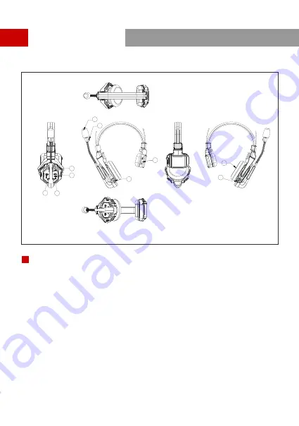
Product Interfaces

1

3

4

5
6

7

 Power/Connection Indicator

Microphone

Power Button

 USB Type-C Interface - For firmware upgrade, and headset pairing

Headset Interfaces

B

Button

Volume - Button

A Button - Lights up when joined Group A, turns off when exited Group A; 

 Long press for 5 seconds to pair

B Button - Lights up when joined Group B, turns off when exited Group B

Battery Compartment

Speaker

B

2

8

9

10

3

Summary of Contents for SOLIDCOM C1

Page 1: ...Quick Guide V1 0 0 HOLLYLAND SOLIDCOM C1 ...

Page 2: ...It is a full duplex wireless DECT intercom system engineered to provide clear audio and all day wearing comfort in a true wireless design with no beltpack required The system operates in the 1 9GHz band 5GWIFI 5190MHz providing a reliable transmission range up to 1000ft 350m radius LOS This Quick Guide will guide you through the installation and use of the equipment FULL DUPLEX WIRELESS INTERCOM S...

Page 3: ...x High gain Antennas 4 x 3 5mm HUB Headset with red nameplate 1 x 12V 2A DC Adapter 2 x USB Type A to Type C Cable 1 x Over ear Cushion 9 x Storage Case 1 x Quick Guide 1 x Warranty Card 1 x Note The amount of the items listed above depends on the edition Battery 1 6 x Microphone Cushion 9 x Packing List 1 ...

Page 4: ...one Jack Join Exit Group B Button for the 3 5mm HUB Headset The indicator turns off when the HUB Headset exit Group B s conversation and turns on in orange after joining in A ANNOUNCE Button Press and hold the button while making an ANNOUNCE release the button when finished Power Switch RF Antenna Interface DC Power Interface PGM Audio Input Interface 2 wire Audio Input Output Interface RJ45 Networ...

Page 5: ...e For firmware upgrade and headset pairing Headset Interfaces B Volume Button Volume Button A Button Lights up when joined Group A turns off when exited Group A Long press for 5 seconds to pair B Button Lights up when joined Group B turns off when exited Group B Battery Compartment Speaker B 2 8 9 10 3 ...

Page 6: ...Product Interfaces Charging Indicator Orange Charging in progress Green Fully charged Charging Contact Charging Case Interfaces c c DC Charging Interface 4 ...

Page 7: ...UB Base Install the HUB antennas Power Up HUB Base Connect the 12V 2A DC Adapter to the HUB base Press the Power Switch to turn on Note The HUB Base can be powered using NP F battery V Mount G Mount battery or DC power supply 5 ...

Page 8: ...n that makes a CLICK sound and the HUB Base s interface displays MUTE corresponding to the headset status 2 Move the mic boom down to the TALK position that makes a CLICK sound and the HUB Base s interface displays TALK corresponding to the headset status TALK MUTE Stop poin t S t o p p o in t The device is now ready for use MUTE TALK 6 Step 1 Slide the battery compartment cover lock Step 2 Open t...

Page 9: ...aces Headset signal strength Headset battery level turns red in low battery Headset number Headset status TALK Headset is active to hear and talk MUTE Headset is muted to hear only LOST Headset lost connection with HUB Base Network connection status WiFi status Quick Start Guide 7 Master ...

Page 10: ... is only required when there is a need for adding or changing headset or HUB base to the system Connect the HUB Base and the Headset with a USB C Cable Pairing requires a USB C cable Connect one end to the USB interface on the HUB Base s front panel and the other end to the USB C interface of the headset The HUB Base screen will display the Select Number interface Locate the designed headset numbe...

Page 11: ...s The Solidcom C1 HUB Base supports two cascading methods 4 wire analog and IP digital signal cascading Generally using 4 wire analog mode to cascade is recommended when cascading two intercom systems If three or more sets are cascaded it is recommended to use IP digital signal cascade It is recommended to use CAT5e super five network cable and RJ45 crystal head with 568B sequence standard for casc...

Page 12: ... mode Enter 4 Wire menu and select Line sequence switching Set to Standard mode HUB 4 Wire Settings HUB Enter 4 Wire menu and select Line sequence switching Set to Cross mode 4 Wire Settings 10 Two Systems Cascade via IP Network Use a standard network cable to connect the two systems through the RJ45 network port Either one of the two RJ45 network ports on the HUB works The network cable is genera...

Page 13: ...omatically to OFF Enter Master and Slave menu and select Master Device HUB Network Settings HUB Enter Network menu and set the Obtain IP address automatically to OFF Enter Master and Slave menu and select Slave Device Network Settings Tap Scan to enter The screen will display the Master Device s IP address Use the Arrow Key to locate the IP address and press Confirm 11 Three Systems Cascade via IP ...

Page 14: ... and connect to the HUB through WiFi to access the Group settings menu Check Group Settings on HUB HUB Display Interfaces Viewing method Operate Grouping via Computer Enter the Network menu on the HUB and select Wired network settings to view the HUB s default IP Address User Name and Password Use a network cable to connect the computer and the HUB via the RJ45 network port Set the IP address of t...

Page 15: ...e buttons light status indicates which group the headset has joined Press the A or B Button on the headset to Join Enter the corresponding group A and B Button Light Status Status Light ON When the A or B Button lights ON it indicates the headset has joined the corresponding group and can converse with the other headset s in the same group Light OFF When the A or B Button lights OFF it indicates t...

Page 16: ...ote headset 10h Charging Time 2 5h Frequency Response Signal to Noise Ratio Distortion Microphone Type Electret Maximum Input Sound Pressure Level Electret Output Sound Pressure Level HUB Base Netweight 1300g antennas excluded Net Weight 170g batteries included Temperature Range Working status 0 45 Storage status 20 60 Note The frequency band and transmit power varies by country and region 35ms 15...

Page 17: ...15 Hollyland Products User Group HollylandTech Support hollyland tech com www hollyland tech com HollylandTech ...

Page 18: ...ation and may not disseminate it in any form All representations information recommendations in this document do not constitute warranties of any kind express or implied Note Due to product version upgrades or other reasons this quick guide will be updated from time to time Unless otherwise agreed this document is provided as a guide for use only All representations information recommendations in ...

Page 19: ...not installed and used in accordance with the instructions may cause harmful interference to radio communications However there is no guarantee that interference will not occur in a particular installation If this equipment does cause harmful interference to radio or television reception which can be determined by turning the equipment off and on the user is encouraged to try to correct the interf...

Reviews: