


BULLETIN 1166
9/4/2015
Page 4 of 20
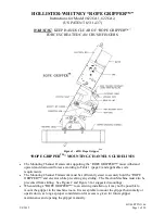
INSTALLATION OF “ROPE GRIPPER
TM
”
Be sure security set screws are holding the rotating shaft in the LOADED (open) position as
shown in Figure 1 on page 1.
Remove both connecting arms after removing the four retaining rings and washers.
Remove movable shoe assembly.
Attach “ROPE GRIPPER™” to mounting channels with appropriate bolts per Table 1 below.
Do not fully tighten bolts yet.
MODEL #
APPROXIMATE
UP & DOWN
FORCE
MOUNTING BOLTS
(Approximate Torques)
REFERENCE
622G (using inch hardware)
4000 lbs
GRADE 5: 1/2" UNC @ 74 ft-lbs
Figure 11
622G (using metric hardware)
17,792 N
GRADE 8.8: M12 @ 100 N*m
Figure 11
Table 1 - Mounting Bolt Sizes and Required Torque
Note: Mounting must conform to applicable codes.
Position the “ROPE GRIPPER™” so that the stationary shoe lining barely touches the ropes
from top to bottom. Make sure “ROPE GRIPPER™” is squarely aligned, and centered side
to side as much as possible, with the ropes. Misalignment may cause uneven and/or
excessive lining wear.
Securely fasten “ROPE GRIPPER™” mounting bolts (5 bolts per side). Make sure they are
torqued correctly. See Table 1.
Double check rope alignment. Make sure the ropes touch the stationary shoe lining evenly.
Reinstall movable shoe assembly.
Reinstall connecting arms with chamfered edges facing the inside of the gripper and secure
the four retaining rings.
Remove Electrical Box cover. Install proper fitting with power and control wiring. See
Diagram 4 or 5 on page 14 or 15.
Connect terminals RG1, RG2, RG5 and RG7 to elevator control. Check control diagram for
proper connection. Connect the Earth ground to the green grounding screw located in the
electrical enclosure.
Make sure controller safety circuit is active and clear for running. Turn
O
perating
M
ode
S
elector (OMS) lever to
Auto Reset
position. Motor may run momentarily and magnet will
energize, causing it to latch on the adjacent gear.
When the magnet is energized, loosen the two security set screws a turn or two. Confirm that
the “ROPE GRIPPER™” is being held open.
Remove the security set screws until there is complete clearance for the rotating shaft to
move up and down the cam (See Figure 7 on page 6).
NOTE: Security set screws must be completely removed when “ROPE GRIPPER™”
activates to prevent gripper failing to set and to prevent damage to the unit.
Unit is now ready for required testing and lining wear-in.


