background image


T i t l e  

Drawing 

No. 

Optical Data Transmission Device for Ethernet 

EWF-0EA/B-N Specification 

C-42-04433 

5


Pin No.


Signal


LEVEL 

GND 

*Connection connector PHR-2 and connection cable are not included. 

If necessary, please contact us separately. 

 
LAN connector (8P): R

J-45 8pin modular jack
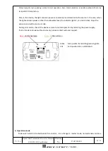


5. Indicator lamp 


*This device contain a circuit which corrects the delay time during high speed stable communication. 

Pin No. 

    MDI Signal 

Signal Function 

TD + 

Transmission Data (+) 

TD - 

Transmission Data (-) 

RD + 

Reception Data (+) 

----- 

Not Used 

----- 

Not Used 

RD - 

Reception Data (-) 

----- 

Not Used 

----- 

Not Used 

P S


L2 L1 C


Socket view 

View from the matting side 

8              1 

Optical axis indicator lamp 

Use to confirm from the opposite side facing device, 

same as level indicator lamp L2 


P: Power supply indicator lamp 

S : Status lamp


(*)   

L2: Level indicator lamp (led up when level margin 2 times)   

L1: Level indicator lamp (led up when level margin 1.5 times)   

C:  Carrier  detection


indicator  lamp  (CD)  (led  up  when  level 

margin 1 time) 

R: Optical link lamp (led up when optical link is established)   


Summary of Contents for EWF-0EA-N

Page 1: ...ended reason Pages Date Corrector Amended No Optical Data Transmission Device for Ethernet EWF 0EA B N Specification C 42 04433 1 9 30th Aug 2019 FA 8271 Supported network Tamaki 19th July 2019 OPTICA...

Page 2: ...hernet line between network cameras and host slave for the communication Communication distance up to 50m converts to optical wireless communication and possible to communicate between moving devices...

Page 3: ...ithout dew frost Ambient illuminance 10000lux or less Halogen mercury lamp Impact resistance 490m s2 X Y and Z directions each 10 times Vibration resistance 10 to 55Hz double amplitude of 1 5mm for 2...

Page 4: ...cuit 1 COM 2 CD 3 VIN 0V Power supply input 4 VIN DC24V Connector pin assignment for level voltage output Model No AWG No Nominal cross section Finished dimension 37104 2206 000FL AWG 20 to 22 0 3 to...

Page 5: ...Signal Signal Function 1 TD Transmission Data 2 TD Transmission Data 3 RD Reception Data 4 Not Used 5 Not Used 6 RD Reception Data 7 Not Used 8 Not Used P S L2 L1 C R Socket view View from the mattin...

Page 6: ...ht emission power is other than allowable level the indicator lights C L1 and L2 blinks Stops the emission and will be in error mode During error mode check if the device returns to normal operation b...

Page 7: ...n OFF of Slave only Slave mode Slave mode Not possible Both link does not connects Does not emits on both side Do not use other operation mode combination than above It may be the reason of data commu...

Page 8: ...eiving Disconnects LAN Link YES NO Slave mode Light receiving Disconnects LAN Link YES NO Light projecting Connected LAN link YES NO Stop emitting Slave mode Emits when light receiving and LAN link is...

Page 9: ...A to adjust so that the level output voltage of B becomes maximum Swing sidewise B to adjust so that the level output voltage of A becomes maximum If a reflector is installed on the optical axis or ne...

Reviews: