Installation 14
HP-313 HRT1
1
The HRT1 outputs a 4-20mA analog signal on the current loop that is
proportional to the calculated flow rate. The 4mA and 20mA settings
referred to as
outLo
and
outHi
respectively, may be configured from
the front panel of the instrument or via HART communications.
3.2
Flowmeter Input
The flowmeter input accepts a low-level sinusoidal signal from a
magnetic type pickup coil, contact closure, or an isolated DC pulse
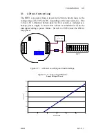
signal. Switches 7, 8, 9 and 10 on SW-2 must be set according to the
type of flowmeter input to be used. Proper switch settings will be made
at the factory if the flowmeter input is specified at the time of order.
SW-2 SWITCH SETTINGS FOR FLOWMETER INPUT OPTIONS:
INPUT OPTION
SW-2 SETTINGS
Mag pickup / Contact Closure
7, 8 AND 9 ON (10 OFF)
Isolated Redi-Pulse - TTL
10 ON (7, 8 AND 9 OFF)
Isolated Redi-Pulse – Open-Collector
10 ON (7, 8 AND 9 OFF)
Magnetic Pickup Coil/Contact Closure
JP2
B
7
2
TB2
10
SIG IN -
11
1
4
SW2
SIG IN +
9
TB1
12
3
8
6
A
Magnetic Pickup
5
Figure 3.2.1 – Magnetic Pickup/Contact Closure Wiring and Switch Settings
SW2
1 2 3 4 5 6 7 8 9 10
NOTE:
HART Communications requires a loop resistance between 250
and 1100 Ohms.
Summary of Contents for HRT1
Page 2: ......
Page 3: ......
Page 4: ......
Page 14: ...Introduction 6 HP 313 HRT1 This Page Intentionally Left Blank...
Page 34: ...Operation and Maintenance 26 HP 313 HRT1 This Page Intentionally Left Blank...
Page 48: ...HART Communications 40 HP 313 HRT1 This Page Intentionally Left Blank...
Page 53: ...Appendix B Declaration of Conformity 45 HRT1 HP 313 APPENDIX B Declaration of Conformity...
Page 54: ...Appendix B Declaration of Conformity 46 HP 313 HRT1...


