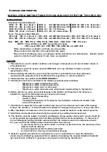
EXTERNAL VIEW
SMALLER HOLE
LARGER HOLE
CONTACT BLADE
NAME LABEL
WIRING
THERMISTOR
LOCK LABEL
*USE ONLY WHEN UTILIZING
TAMPER LOCK FACILITY
[Fig.1]
The wiring diagram for the detector base should be made as shown in Fig.2
[STANDARD CONFIGURATIONS)
CONVENTIONAL
CONTROL PANEL
___ ___J
+
YBN TYPE
[Fig.2]
HOW TO USE DETECTOR HEAD REMOVER
1. In case of detector head mounting to the base.
3
REMOTE
LAMP
YBO TYPE
a) Fit and insert the 2 push rods of the remover to the holes on the detector.
NEXT
DETECTOR
ON
ZONE
b) Gently push the remover with detector to the detector base and twist clockwise for secure fitting
of the detector head and base.
2. In case of detector removal from the base.
a) Fit and insert the 2 push rods of the remover
to the holes on the detector.
b) Twist counterclockwise for removal of the detector head from the base.
HOW TO USE THE TAMPER LOCK OF THE DETECTOR
1. Remove prong located back side of the detector and put the LOCK label on the side of the detector.
( The label is packed together with the detector. )
2. Mount the detector to the base bringing alignment marks on the detector and base into line for
secure tamper locking.
3. Tamper locked detector can be removed from the base by the detector remover which has a
mechanism to release the tamper lock.
HOW TO REMOVE THE TAMPER LOCKED DETECTOR
1.
Fit
and insert the larger and smaller push rods of the remover for tamper lock releasing
to the holes
on the detector. Larger hole is located by the indication of " DO NOT PAINT " on the detector.
2. Push the remover towards detector to release the tamper lock and twist counterclockwise
to remove
the detector head from the base.
DETECTOR
DETECTOR
(Fig.3)
HAU 2-5-001/ISS1/FEB19


