HOBO MX Analog/Temp/RH/Light (MX1104) and MX 4-Channel Analog (MX1105) Manual
1-508-759-9500 (U.S. and International)
1-800-LOGGERS (564-4377) (U.S. only)
www.onsetcomp.com/support/contact
© 2019–2022 Onset Computer Corporation. All rights reserved. Onset, HOBO, HOBOconnect, and HOBOlink are
registered trademarks of Onset Computer Corporation. App Store, iPhone, iPad, and iPadOS are service marks or
registered trademarks of Apple Inc. Android and Google Play are trademarks of Google LLC. Windows is a registered
trademark of Microsoft Corporation. Bluetooth and Bluetooth Smart are registered trademarks of Bluetooth SIG,
Inc. All other trademarks are the property of their respective companies.
Patent #: 8,860,569
23968-H
to signals below 0 V or above 2.5 V. The voltage input
cable connections are as follows:
Wire Connection
Red
Switched 2.5 V output
White Voltage
input
Black Ground
•
The external input channels have a switched 2.5 V
output. This signal can be used to power a sensor directly
or to trigger an external circuit. External sensors should
draw no more than 4 mA total when powered.
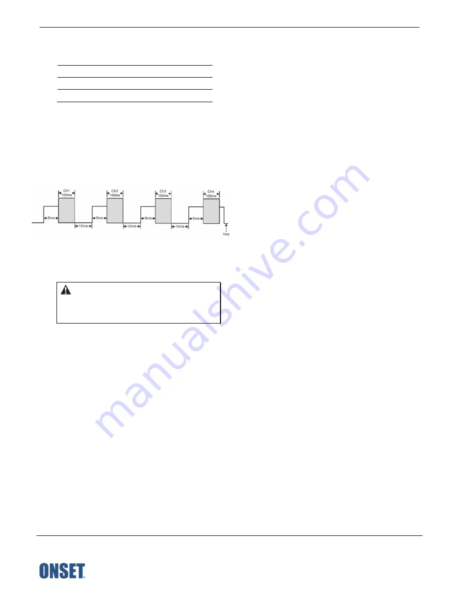
The switched 2.5 V output turns on about 5 ms before
the external channels are measured as shown in the
following diagram for an MX1105 logger. The shaded
area shows the 100 ms period for each enabled channel
during which the logger samples the input signals.
When using multiple voltage and/or current inputs, the
(-) from the current source(s) and the 0 V line from the
voltage source(s) are tied together at the logger. If these
lines are at different voltage potentials, this may cause
inaccurate readings or even damage your logger.
WARNING:
Analog channel input cannot exceed 2.5
V DC. For sensor outputs up to 24 V DC, use the
appropriate voltage adapter cable (SD-VOLT-xx or
CABLE-ADAPX).
Setting up Alarms
You can set an alarm to trip on the logger when a sensor
reading rises above or falls below a specified value. Alarms alert
you to problems so you can take corrective action. To set an
alarm:
1.
Tap Devices.
2.
Tap the logger tile in the app to connect to the logger and
tap Configure & Start.
3.
Tap a Sensor/Channel.
4.
Tap Enable Logging, if necessary.
5.
Tap Alarms to open that area of the screen.
6.
Select Low if you want an alarm to trip when the sensor
reading falls below the low alarm value. Enter a value to set
the low alarm value.
7.
Select High if you want an alarm to trip when the sensor
reading rises above the high alarm value. Enter a value to
set the high alarm value.
8.
For the Duration, select how much time should elapse
before the alarm trips and select one of the following:
•
Cumulative Samples. The alarm trips once the sensor
reading is out of the acceptable range for the selected
duration any time during logging. For example, if the high
alarm is set to 85°F and the duration is set to 30 minutes,
the alarm trips once the sensor readings have been
above 85°F for a total of 30 minutes since the logger was
configured.
•
Consecutive Samples. The alarm trips once the sensor
reading is out of the acceptable range continuously for
the selected duration. For example, the high alarm is set
to 85°F and the duration is set to 30 minutes, the alarm
trips only if all sensor readings are 85°F or above for a
continuous 30-minute period.
9.
Repeat steps 2–8 for the other sensor.
10.
In the Alarm Settings area, enable Audible Alarm if you
want the logger to beep every 30 seconds when the sensor
alarm trips. The beeping continues until you clear the alarm
in the app, press either button on the top of the logger, or 7
days have passed. Battery life is slightly reduced when this
setting is enabled. It is recommended that you enable this
feature only if you have regular access to the logger so that
you can easily turn off the beeping.
11.
For Show Visual Alarms Until, select one of the following
options to determine how long the alarm icon remains
illuminated on the logger LCD screen after an alarm trips:
•
Logger Reconfigured.
The alarm icon remains visible on
the LCD until the next time the logger is reconfigured.
•
Sensor in Limits.
The alarm icon remains visible on the
LCD until the sensor reading returns to the normal range
between any configured high and low alarm limits.
•
Alarm Button Pressed.
The alarm icon remains visible
until you press the Alarm/Stats button on the logger.
Notes:
•
The alarm icon is illuminated on the logger LCD when the
alarm trips. You can also press the Alarms/Stats button
on the logger to view the farthest out-of-range value
during the deployment. Dashes appear instead of a value
once the alarm is cleared on the channel. The logger
checks alarm limits at the same rate as the logging
interval.
•
The actual values for the high and low alarm limits are set
to the closest value supported by the logger. In addition,
alarms can trip or clear when the reading is within the
resolution specifications. This means the value that
triggers the alarm may differ slightly from the value
entered.
•
When you download data from the logger, alarm events
can be displayed on the plot or in the data file. See
Logger Events
.
•
Once cleared, an audible alarm will start beeping again if
the sensor values go out of the normal range. Even if you
clear an audible alarm, a visual alarm may remain on the
logger LCD and in the app depending on the settings
selected for Show Visual Alarms Until or because the
alarm condition may still be in effect. In addition, an


