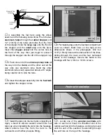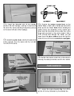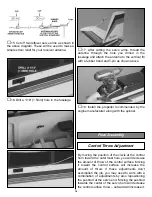
attitude as the plane descends.
Maintain
approximately 1/3rd throttle until you are above the
end of the runway. At this point you should be at an
altitude of approximately ten feet. Now is the time to
decrease the throttle to just above idle, maintain a
level wing attitude and flare the airplane to a smooth
touch down by pulling back on the elevator stick.
Have a ball! But always stay in control and fly
in a safe manner.
Note: The following article has been reprinted in part for
future reference and also as a guide for your flight
instructor or experienced flying partner to help you with
trimming your model. If further information is required,
please contact your local hobby dealer, local flying club
or call Great Planes at (217) 398-8970.
A model is not a static object. Unlike a car, which
you can only hunt left or right on the road (technically, a
car does yaw in corners, and pitches when the brakes
are applied), a plane moves through that fluid we call air
in all directions simultaneously. The plane may look like
it’s going forward, but it could also be yawing slightly,
slipping a little and simultaneously climbing or diving a
bit! The controls interact. Yaw can be a rudder problem,
a lateral balance problem or an aileron rigging problem.
We must make many flights, with minor changes
between each, to isolate and finally correct the problem.
The chart accompanying this article is intended to
serve as a handy field reference when trimming your
model. Laminate it in plastic and keep it in your flight box.
You just might have need to consult it at the next contest!
The chart is somewhat self-explanatory, but we will
briefly run through the salient points.
First, we are assuming that the model has been
C.G.
balanced according to the manufacturer’s
directions. There’s nothing sacred about that spot –
frankly, it only reflects the balance point where a
prototype model handled the way the guy who designed
it thought it should. If your model’s wing has a degree
more or less of incidence, then the whole balance
formula is incorrect for you. But, it’s a good ballpark place
to start.
The second assumption is that the model has been
balanced laterally. Wrap a strong string or monofilament
around the prop shaft behind the spinner, then tie the
other end to the tail wheel or to a screw driven into the
bottom of the aft fuse. Make the string into a bridle
harness and suspend the entire model inverted (yes,
with the wing on!). If the right wing always drops, sink
some screws or lead into the left wing tip, etc. You may
be surprised to find out how much lead is needed.
At this point the model is statically trimmed. It’s only
a starting point, so don’t be surprised if you wind up
changing it all. One other critical feature is that the
ailerons must have their hinge gap sealed. If shoving
some Scotch
®
tape or MonoKote
®
into the hinge gap to
prevent the air from slipping from the top of the wing to
the bottom, and vice-versa, bothers you, then don’t do it.
To achieve the maximum lateral trim on the model,
the hinge gap on the ailerons should be sealed. The
easiest way to do this is to disconnect the aileron
linkages, and fold the ailerons as far over the top of the
wing as possible (assuming they are top or center
hinged). Apply a strip of clear tape along the joint line.
When the aileron is returned to neutral, the tape will be
invisible, and the gap will be effectively sealed.
Depending on how big the ailerons are, and how large a
gaping gap you normally leave when you install hinges,
you could experience a 20 percent increase in aileron
control response just by this simple measure.
Your first flights should be to ascertain control
centering and control feel. Does the elevator always
come back to neutral after a 180° turn or Split-S? Do the
ailerons tend to hunt a little after a rolling maneuver? Put
the plane through its paces. Control centering is either a
mechanical thing (binding servos, stiff linkages, etc.), an
electronic thing (bad servo resolution or dead band in
the radio system), or C.G. (aft Center of Gravity will
make the plane wander a bit). The last possibility will be
obvious, but don’t continue the testing until you have
isolated the problem and corrected it.
Let’s get down to the task of trimming the model.
Use the tachometer every time you start the engine, to
insure consistent results. These trim flights must be done
in calm weather. Any wind will only make the model
weather vane. Each “maneuver” on the list assumes that
you will enter it dead straight-and-level. The wings must
be perfectly flat, or else the maneuver will not be correct
and you’ll get a wrong interpretation. That’s where your
observer comes in. Instruct him to be especially watchful
of the wings as you enter the maneuvers.
Do all maneuvers at full throttle. The only deviation
from this is if the plane will routinely be flown through
maneuvers at a different power setting.
Let’s commence with the “engine thrust angle” on
the chart. Note that the observations you make can also
be caused by the C.G., so be prepared to change both
to see which gives the desired result. Set up a straight-
and-level pass. The model should be almost hands-off.
Without touching any other control on the transmitter,
suddenly chop the throttle. Did the nose drop? When you
add power again, did the nose pitch up a bit? If so, you
need some down thrust, or nose weight. When the thrust
Flight Trimming
Appendix
21


