Hobbico FlyZone Aero Voyager Assembly Instructions Manual Download Page 11

Switch off the airplane. Then, switch the transmitter off.
Unplug the battery from the plane and remove it from
the battery compartment. Allow the motors and battery
to cool before recharging. Check the plane over to make
sure nothing has come loose or may be damaged.

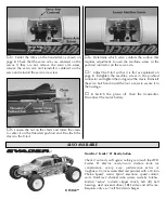
To order replacement parts for your Aero Voyager, use the
order  numbers  in  the  list  below.  Replacement  parts  are
available  only  as  listed.  Replacement  parts  are  not
available from Product Support, but can be purchased from
hobby shops or mail order/Internet order firms. If you need
assistance locating a dealer to purchase parts, contact: 

Product Support

Phone: 217-398-0007

Fax: 217-398-7721

E-mail: [email protected]

Before starting to build, take an inventory of this kit to
make sure it is complete and inspect the parts to make
sure  they  are  of  acceptable  quality.  If  any  parts  are
missing or are not of acceptable quality, or if you need
assistance  with  assembly,  contact  Product  Support.
When reporting defective or missing parts, use the part
names exactly as they are written in the parts list.

Stock #

Description

HCAA3413

Main Wing Kit

HCAA3414

Tail Assembly Kit

HCAA3415

Decals

HCAA3416

Fuse Set w/Pushrods

HCAA3417

Servo Hatch Door

HCAA3507

Canopy (Hatch)

HCAA3510

Motor Pod

HCAG1012

Motors (2)

HCAM7024

Battery NiMH

HCAM7106

TX Antenna

HCAP9918

12V Field Charger

HCAQ3303

Propellers (4)

Even the best R/C pilots in the world damage their planes
every  now  and  then.  In  the  unfortunate  event  that  you
damage your airplane, repairs are fairly simple to make
yourself. If there are any cracks in the wing or fuselage,
apply 6-minute epoxy or white glue to the broken area
and hold together with clear packaging tape. Let the glue
cure, leaving the tape in place for added strength.
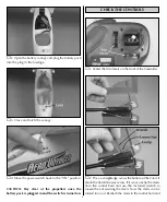
❏ 

1. Remove the four screws that hold the servo hatch

on the bottom of the fuselage.

❏ 

2.  Remove  the  hatch.  The  decals  may  need  to  be

trimmed from around the hatch to allow it to be removed.

❏ 

3.  Switch  on  the  transmitter,  plug  the  motor  battery

into the connector inside the fuselage and switch on the
plane. 

CAUTION: Stay clear of the propellers.
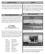
SERVO ADJUSTMENT

REPAIRS

REPLACEMENT PARTS LIST

AFTER THE FLIGHT

11

Summary of Contents for FlyZone Aero Voyager

Page 1: ...ity shall be assumed nor accepted for any damage resulting from the use by the user of the final user assembled product By the act of using the user assembled product the user accepts all resulting li...

Page 2: ...modifications you will void your warranty 2 Test the operation of the model before each flight to insure that all equipment is operating properly and that the model remains structurally sound 3 Fly o...

Page 3: ...g 1 5 V Tail 1 6 Transmitter 1 7 Wrench for Tightening Nuts 1 8 Nuts 2 9 Tail Skid 1 10 Rubber Bands 4 Spare Propellers Not Shown in Photo 2 Decal Not Shown in Photo 1 Instructional DVD Not Shown in P...

Page 4: ...n the mounting bolts that extend through the bottom of the tail boom as shown in the photo Using the included wrench tighten the nuts firmly but do not overtighten You have now completed the assembly...

Page 5: ...the contacts in the transmitter case Reinstall the battery hatch on the transmitter case and tighten the screw 4 Switch on the transmitter and check the LED on the front of the transmitter If the gre...

Page 6: ...e battery into the charger there is no way to know how much charge is left in the battery unless you have just completed a flight in which the battery was run all the way down or have fully discharged...

Page 7: ...k is charged open the battery hatch canopy Insert the battery pack inside the fuselage Do not plug the battery pack into the connector inside the fuselage Close the canopy 2 Place marks on the bottom...

Page 8: ...k is plugged in and the switch is turned on 1 Center the trim levers on the front of the transmitter 2 Place a straightedge across the bottom of the V tail It should be flat all the way across If it i...

Page 9: ...e the right stick on the transmitter to the left The left control surface will go down and the right control surface will go up The plane will turn to the left 8 To start the motors the throttle lever...

Page 10: ...d before turning 3 To turn the Aero Voyager move the right stick to the left or right slightly The more you move the stick the tighter the turn will be To stop the turn move the stick the opposite dir...

Page 11: ...defective or missing parts use the part names exactly as they are written in the parts list Stock Description HCAA3413 Main Wing Kit HCAA3414 Tail Assembly Kit HCAA3415 Decals HCAA3416 Fuse Set w Pus...

Page 12: ...8 Retighten the machine screw in the pushrod connector and tighten the nut against the clevis Reinstall the servo hatch and install the four screws to secure it to the fuselage 8 Switch the plane off...

Reviews: