


10
BALANCE THE MODEL (C.G.)
More than any other factor, the
C.G.
(balance point) can
have the
greatest
eff ect on how a model fl ies and may
determine whether or not your fi rst fl ight will be successful.
If you value this model and wish to enjoy it for many fl ights,
DO NOT OVERLOOK THIS IMPORTANT PROCEDURE
. A
model that is not properly balanced will be unstable and
possibly unfl yable.
At this stage the model should be in ready-to-fl y condition
with all of the systems in place including the engine, landing
gear, covering and the radio system.
❍
1. Use a felt-tip pen or 1/8"-wide tape to accurately mark
the C.G. on the top of the wing. The C.G. is located 118
mm (4.6 ") back from the leading edge of the wing.
❍
2. With the wing attached to the fuselage, all parts of
the model installed (ready to fl y) and with batteries in
position, place the model upside-down on a Great Planes
CG Machine, or lift it upside-down at the balance point
you marked.
❍
3. If the tail drops, the model is “tail heavy” and the battery
pack and/or receiver must be shifted forward or weight
must be added to the nose to balance. If the nose drops,
the model is “nose heavy” and the battery pack and/or
receiver must be shifted aft or weight must be added to
the tail to balance. If possible, relocate the battery pack
and receiver to minimize or eliminate any additional
ballast required. If additional weight is required, nose
weight may be easily added by using a “spinner weight”
(GPMQ4645 for the 1 oz. weight, or GPMQ4646 for the
2 oz. weight). If spinner weight is not practical or is not
enough, use Great Planes (GPMQ4485) “stick-on” lead. A
good place to add stick-on nose weight is to the fi rewall
(don't attach weight to the cowl–it is not intended
to support weight). Begin by placing incrementally
increasing amounts of weight on the bottom of the fuse
over the fi rewall until the model balances. Once you
have determined the amount of weight required, it can
be permanently attached. If required, tail weight may be
added by cutting open the bottom of the fuse and gluing
it permanently inside.
GET THE MODEL READY TO FLY
CHECK THE CONTROL DIRECTIONS
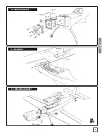
❏
1. Turn on the transmitter and receiver and center the
trims. If necessary, remove the servo arms from the servos and
reposition them so they are centered. Reinstall the screws that
hold on the servo arms.
❏
2. With the transmitter and receiver still on, check all the
control surfaces to see if they are centered. If necessary, adjust
the clevises on the pushrods to center the control surfaces.
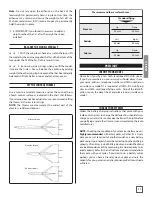
VOLLGAS
SEITENRUDER
GEHT NACH
RECHTS
HÖHENRUDER GEHT
NACH UNTEN
LINKES QUERRUDER
GEHT NACH UNTEN,
RECHTES NACH OBEN
4-KANAL STEUERUNG
(STANDARD MODE 1)
VOLLGAS
SEITENRUDER
GEHT NACH
RECHTS
HÖHENRUDER GEHT
NACH UNTEN
LINKES QUERRUDER
GEHT NACH UNTEN,
RECHTES NACH OBEN
4-KANAL STEUERUNG
(STANDARD MODE 2)
❏
3. Make certain that the control surfaces and the carburetor
respond in the correct direction as shown in the diagram. If any
of the controls respond in the wrong direction, use the servo
reversing in the transmitter to reverse the servos connected to
those controls. Be certain the control surfaces have remained
centered. Adjust if necessary.
ENGLISH


