


INSTALLATION
Page
8
II Water
supply
A water supply pipe with a “Stop cock” (see “Glossary”) must be provided for each machine.
The water supply line must conform to the specifications indicated
in the section “Installation data”, even when other appliances are
connected to the supply line.
If the water supply system is new or has not been used for a
prolonged period, run the water before connecting the
appliance so as to eliminate any impurities or air pockets which
could soil or damage the machine.
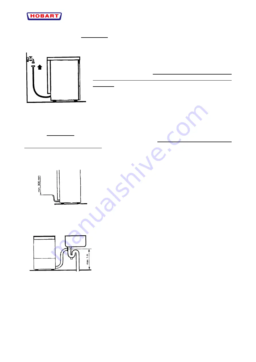
Connect the filling solenoid valve to the stop cock with a flexible
pipe.
III Drain
line
A suitable “Drain line” must be provided (see “Glossary”).
To ensure unrestricted discharge the pipe must reach the trap without being put under tension,
kinked, crushed, pressed or forced.
Drain Pump is standard on model EF40
If the discharge pipe is connected to a trap in the floor, the
highest point of the pipe must be at least 300 mm above floor
level to prevent the machine from emptying.
The highest point of the discharge pipe should be less than 1
meter above floor level.
EF 40
Summary of Contents for CHF 45
Page 1: ......


