background image

OM-235 281 Page 3

1-3. Additional Symbols For Installation, Operation, And Maintenance

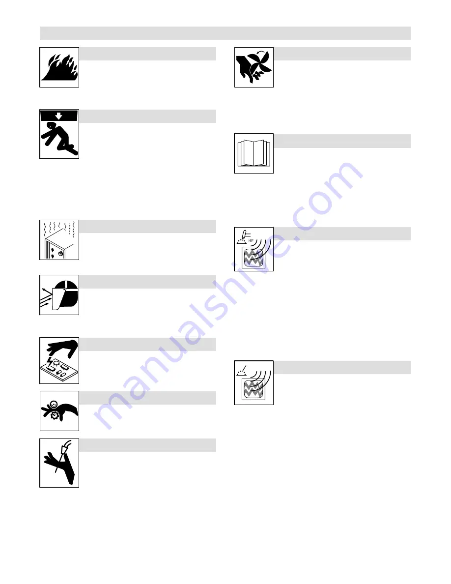
FIRE OR EXPLOSION hazard.

D

Do not install or place unit on, over, or near

combustible surfaces.

D

Do not install unit near flammables.

D

Do not overload building wiring 

 be sure power supply system is

properly sized, rated, and protected to handle this unit.

FALLING EQUIPMENT can injure.

D

Use lifting eye to lift unit only, NOT running

gear, gas cylinders, or any other accessories.

D

Use equipment of adequate capacity to lift and

support unit.

D

If using lift forks to move unit, be sure forks are long enough to

extend beyond opposite side of unit.

D

Keep equipment (cables and cords) away from moving vehicles

when working from an aerial location.

D

Follow the guidelines in the Applications Manual for the Revised

NIOSH Lifting Equation (Publication No. 94

110) when manu-

ally lifting heavy parts or equipment.

OVERUSE can cause OVERHEATING

D

Allow cooling period; follow rated duty cycle.

D

Reduce current or reduce duty cycle before

starting to weld again.

D

Do not block or filter airflow to unit.

FLYING SPARKS can injure.

D

Wear a face shield to protect eyes and face.

D

Shape tungsten electrode only on grinder with

proper guards in a safe location wearing proper

face, hand, and body protection.

D

Sparks can cause fires — keep flammables away.

STATIC (ESD) can damage PC  boards.

D

Put on grounded wrist strap BEFORE handling

boards or parts.

D

Use proper static-proof bags and boxes to

store, move, or ship PC boards.

MOVING PARTS can injure.

D

Keep away from moving parts.

D

Keep away from pinch points such as drive

rolls.

WELDING WIRE can injure.

D

Do not press gun trigger until instructed to do

so.

D

Do not point gun toward any part of the body,

other people, or any metal when threading

welding wire.

MOVING PARTS can injure.

D

Keep away from moving parts such as fans.

D

Keep all doors, panels, covers, and guards

closed and securely in place.

D

Have only qualified persons remove doors, panels, covers, or

guards for maintenance and troubleshooting as necessary.

D

Reinstall doors, panels, covers, or guards when maintenance is

finished and before reconnecting input power.

READ INSTRUCTIONS.

D

Read and follow all labels and the Owner’s

Manual carefully before installing, operating, or

servicing unit. Read the safety information at

the beginning of the manual and in each

section.

D

Use only genuine replacement parts from the manufacturer.

D

Perform maintenance and service according to the Owner’s

Manuals, industry standards, and national, state, and local

codes.

H.F. RADIATION can cause interference.

D

High-frequency (H.F.) can interfere with radio

navigation, safety services, computers, and

communications equipment.

D

Have only qualified persons familiar with

electronic equipment perform this installation.

D

The user is responsible for having a qualified electrician prompt-

ly correct any interference problem resulting from the installa-

tion.

D

If notified by the FCC about interference, stop using the

equipment at once.

D

Have the installation regularly checked and maintained.

D

Keep high-frequency source doors and panels tightly shut, keep

spark gaps at correct setting, and use grounding and shielding to

minimize the possibility of interference.

ARC WELDING can cause interference.

D

Electromagnetic energy can interfere with

sensitive electronic equipment such as

computers and computer-driven equipment

such as robots.

D

Be sure all equipment in the welding area is

electromagnetically compatible.

D

To reduce possible interference, keep weld cables as short as

possible, close together, and down low, such as on the floor.

D

Locate welding operation 100 meters from any sensitive elec-

tronic equipment.

D

Be sure this welding machine is installed and grounded

according to this manual.

D

If interference still occurs, the user must take extra measures

such as moving the welding machine, using shielded cables,

using line filters, or shielding the work area.

Summary of Contents for H200L4-15 Gun

Page 1: ...IronMan 230 And H200L4 15 Gun Processes OM 235 281B 2010 04 Gas Metal Arc MIG Welding Flux Cored Arc FCAW Welding Description Arc Welding Power Source and Wire Feeder File MIG GMAW ...

Page 2: ...oducts Please take time to read the Safety precautions They will help you protect yourself against potential hazards on the worksite We ve made installation and operation quick and easy With Hobart you can count on years of reliable service with proper maintenance And if for some reason the unit needs repair there s a Troubleshooting section that will help you figure out what the problem is The pa...

Page 3: ...3 7 Setting Gun Polarity For Wire Type 15 3 8 Installing 2 lb Wire Spool And Adjusting Hub Tension 15 3 9 Installing 10 lb Wire Spool And Adjusting Hub Tension 16 3 10 Installing 33 lb Wire Spool And Adjusting Hub Tension 16 3 11 Installing Gas Supply 17 3 12 Positioning Jumper Links 18 3 13 Electrical Service Guide 19 3 14 Serial Number And Rating Label Location 20 3 15 Selecting A Location And C...

Page 4: ... Weld Bead Characteristics 35 6 8 Troubleshooting Excessive Spatter 36 6 9 Troubleshooting Porosity 36 6 10 Troubleshooting Excessive Penetration 36 6 11 Troubleshooting Lack Of Penetration 37 6 12 Troubleshooting Incomplete Fusion 37 6 13 Troubleshooting Burn Through 37 6 14 Troubleshooting Waviness Of Bead 38 6 15 Troubleshooting Distortion 38 6 16 Common MIG Shielding Gases 39 6 17 Troubleshoot...

Page 5: ...olds when in cramped positions such as sitting kneeling or lying or when there is a high risk of unavoid able or accidental contact with the workpiece or ground For these conditions use the following equipment in order presented 1 a semiautomaticDC constant voltage wire welder 2 a DC manual stick welder or 3 an AC welder with reduced open circuit volt age In most situations use of a DC constant vo...

Page 6: ...nless they are properly prepared according to AWS F4 1 see Safety Standards D Do not weld where the atmosphere may contain flammable dust gas or liquid vapors such as gasoline D Connect work cable to the work as close to the welding area as practical to prevent welding current from traveling long possibly unknown paths and causing electric shock sparks and fire hazards D Do not use welder to thaw ...

Page 7: ... panels covers and guards closed and securely in place D Have only qualified persons remove doors panels covers or guards for maintenance and troubleshooting as necessary D Reinstall doors panels covers or guards when maintenance is finished and before reconnecting input power READ INSTRUCTIONS D Read and follow all labels and the Owner s Manual carefully before installing operating or servicing u...

Page 8: ... web site www ansi org Standard for Fire Prevention During Welding Cutting and Other Hot Work NFPA Standard 51B from National Fire Protection Association Quincy MA 02269 phone 1 800 344 3555 website www nfpa org OSHA Occupational Safety and Health Standards for General Indus try Title 29 Code of Federal Regulations CFR Part 1910 Subpart Q and Part 1926 Subpart J from U S Government Printing Office...

Page 9: ...urant électrique s avère nécessaire se servir de la fonction de télécommande si l appareil en est équipé D D autres consignes de sécurité sont nécessaires dans les condi tions suivantes risques électriques dans un environnement humideou si l on porte des vêtements mouillés sur des structures métalliquestelles que sols grilles ou échafaudages en position coincée comme assise à genoux ou couchée ou ...

Page 10: ... ou laine et des bottes de protection LE SOUDAGE peut provoquer un incendie ou une explosion Le soudage effectué sur des conteneurs fermés tels que des réservoirs tambours ou des conduites peut provoquer leur éclatement Des étincelles peuvent être projetées de l arc de soudure La projection d étincelles des pièces chaudes et des équipements chauds peut provoquer des incendies et des brûlures Le co...

Page 11: ...ur D Utiliser les équipements corrects les bonnes procédures et suffi samment de personnes pour soulever et déplacer les bouteilles D Lire et suivre les instructions sur les bouteilles de gaz comprimé l équipement connexe et le dépliant P 1 de la CGA Compressed Gas Association mentionné dans les principales normes de sécu rité 2 3 Dangers supplémentaires en relation avec l installation le fonction...

Page 12: ...ecte et utiliser une terre et un blindage pour réduire les interférences éventuelles LE SOUDAGE À L ARC risque de provoquer des interférences D L énergie électromagnétique risque de provoquer des interférences pour l équipement électroniquesensible tel que les ordinateurs et l équipement commandé par ordinateur tel que les robots D Veiller à ce que tout l équipement de la zone de soudage soit comp...

Page 13: ...n 5 Chicago est 312 353 2220 site Internet www osha gov U S Consumer Product Safety Commission CPSC 4330 East West Highway Bethesda MD 20814 téléphone 301 504 7923 site inter net www cpsc gov Applications Manual for the Revised NIOSH Lifting Equation The National Institute for Occupational Safety and Health NIOSH 1600 Clifton Rd Atlanta GA 30333 télé hone 1 800 232 4636 site internet www cdc gov N...

Page 14: ...OM 235 281 Page 10 ...

Page 15: ...84 kg 023 045 in 0 6 1 2 mm 030 035 in 0 8 0 9 mm 030 045 in 0 8 1 2 mm 3 2 Welding Power Source Duty Cycle And Overheating Duty Cycle is percentage of 10 min utes that unit can weld at rated load without overheating If unit overheats thermostat s opens output stops and cooling fan runs Wait fifteen minutes for unit to cool Reduce amperage or voltage or duty cycle before welding NOTICE Exceeding d...

Page 16: ...amperecurves show minimum and maximum voltage and amper age output capabilities of unit Curves of other settings fall be tween curves shown va_curve1 4 95 240 913 A 0 0 5 0 10 0 15 0 20 0 25 0 30 0 35 0 40 0 0 50 100 150 200 250 300 Voltage Amperage ...

Page 17: ...mbly 2 Gun Securing Knob 3 Gun End Loosen knob Insert gun end through opening until it bottoms against drive assembly Tighten knob 4 Gun Trigger Plug Insert plug into receptacle and tighten threaded collar 5 MIG Spool Gun Switch Switch is shown in MIG position Close door 3 4 2 1 SPOOL GUN MIG GUN 5 ...

Page 18: ...re with nut so that weld cable terminal is tight against copper bar Do not place anything between weld cable terminal and copper bar Make sure that the surfaces of the weld cable terminal and copper bar are clean Tools Needed 3 4 in 19 mm 4 2 3 Do not place anything between Correct Installation Incorrect Installation 1 weld cable terminal and copper bar 3 6 Installing Work Clamp 1 Work Cable Route...

Page 19: ...bove for gasless flux core wires FCAW Drive assembly becomes negative Positive Terminal Negative Terminal Work Clamp Lead Wire Drive Assembly Lead Changing Polarity 3 8 Installing 2 lb Wire Spool And Adjusting Hub Tension 242 146 A 1 Keyed Washer 2 Wire Spool 2 LB 3 Keyed Washer 4 Compression Spring 5 Washer 6 Nut Assemble components in numer ical order as shown Hand tighten nut to create a slight...

Page 20: ...t to create a slight drag while rotating wire spool Over tightening nut may cause wire slippage 2 1 3 4 5 6 7 3 10 Installing 33 lb Wire Spool And Adjusting Hub Tension 242 148 A 1 Spool Hub 2 Spool Hub Adapter 3 Spool Hub Nut 4 Keyed Washer 2 5 Compression Spring 6 Washer 7 Nut Assemble components in numer ical order as shown Slide spool hub adapter up on hub for the smaller spool making sure it ...

Page 21: ...Gas flow blows dust and dirt from valve Close valve 3 Cylinder a Argon Or Mixed Gas Cylinder b CO2 Cylinder 4 Regulator Flowmeter a Argon Or Mixed Gas Regulator Flowmeter b CO2 Regulator Flowmeter Install so face is vertical 5 Regulator Flowmeter Gas Hose Connection 6 Welding Power Source Gas Hose Connection For MIG Gun Connect supplied gas hose between regulator flowmeter gas hose connection and ...

Page 22: ...t power Check input voltage available at site 1 Jumper Links Access Door Open door 2 Jumper Link Label Check label only one is on unit 3 Input Voltage Jumper Links Move jumper links to match input voltage Close and secure access door 3 Tools Needed 2 3 8 in 200 VOLTS 230 VOLTS S 153 980 1 ...

Page 23: ...Length In Feet Meters 77 23 102 31 Min Grounding Conductor Size In AWG 4 10 10 Reference 2008 National Electrical Code NEC including article 630 1 If a circuit breaker is used in place of a fuse choose a circuit breaker with time current curves comparable to the recommended fuse 2 Time Delay fuses are UL class RK5 See UL 248 3 Normal Operating general purpose no intentional delay fuses are UL clas...

Page 24: ...before connecting input conductors from unit Always connect green or green yel low conductor to supply grounding terminal first and never to a line terminal 4 Plug NEMA Type 6 50P 5 Receptacle NEMA Type 6 50R Connect plug to receptacle 6 Input Power Cord 7 Black And White Input Conductor L1 And L2 8 Green Or Green Yellow Grounding Conductor 9 Disconnect Device switch shown in the OFF position 10 D...

Page 25: ...hold wire cut off end Push wire thru guides into gun continue to hold wire Close and tighten pressure assembly and let go of wire Lay gun cable out straight and remove gun nozzle and contact tip Turn power ON Press gun trigger until wire comes out of gun Reinstall contact tip and nozzle Feed wire to check drive roll pressure Tighten knob enough to prevent slipping Cut off wire approximately 5 16 i...

Page 26: ... Gun Trigger Plug Insert plug into receptacle and tighten threaded collar 6 Spool Gun MIG Gun Switch Place switch in Spool Gun position 7 Polarity Change Over Terminal Block To make proper polarity connection see Section 3 7 Close door 8 Wire Feed Speed Control Wire feed speed is controlled by welding power source Wire Feed Speed control see Section 4 1 9 Voltage Control Arc voltage is controlled ...

Page 27: ...evel of the welding arc The voltage range is 1 minimum to 12 maximum 3 Power Switch The fan is thermostatically controlled and only runs when cooling is needed 4 Power Light 5 Gun Trigger Receptacle 1 Ref 242 155 A 2 4 TRIGGER POWER ON OFF POWER DO NOT SWITCH WHILE WELDING WIRE FEED VOLTAGE ÇÇÇÇÇ ÇÇÇÇÇ ÇÇÇÇÇ ÇÇÇÇÇ ÇÇÇÇÇ 0 1 12 10 9 8 7 6 5 4 3 2 10 20 30 40 50 60 70 80 90 100 OFF 3 5 ...

Page 28: ...ge Setting Number on Right is Wire Feed Setting 1 2 inch 12 7mm 9 62 6 38 7 30 7 70 7 54 6 32 8 70 7 46 6 34 8 62 8 60 8 78 10 70 7 54 8 50 9 50 10 66 11 60 12 34 12 98 12 82 12 42 8 74 8 70 7 50 6 34 9 62 6 38 7 30 7 70 7 54 6 32 8 70 7 46 6 34 8 62 8 60 7 76 10 70 7 54 8 50 8 44 9 60 10 52 11 30 10 82 10 58 11 38 3 8 inch 9 5mm 7 70 7 60 6 44 6 34 9 90 8 50 6 38 7 30 7 70 7 54 6 32 7 60 7 46 6 3...

Page 29: ...ghten Weld Terminal Every 6 Months OR Inside Unit n Remove drive roll and apply light coat of oil or grease to drive motor shaft 5 2 Supplementary Protectors Ref 242 160 A Turn Off unit 1 Supplementary Protector CB1 CB1 protects main circuit board PC1 2 Supplementary Protector CB2 CB2 protects the drive motor circuit from overload If drive motor shorts or fails check gun liner blockage or kinks ch...

Page 30: ...opposite side of the drive roll The groove closest to the motor shaft is the proper groove to thread wire see Section 3 16 4 Drive Roll Securing Nut Turn nut one click to secure drive roll 1 2 3 4 5 4 Removing Knob From Front Panel Turn Off power 1 Front Panel 2 Knob 3 Spring Clip 4 Control Shaft 5 Slot Rotate knob to allow access to slot Insert Allen wrench or stiff piece of wire into slot and wh...

Page 31: ...e Gear Insert screwdriver and turn screw in or out until drive roll groove lines up with wire guide Close pressure roll assembly Ref 800 412 A Correct Incorrect 4 3 2 1 5 Tools Needed 5 6 Replacing Gun Contact Tip Ref 242 164 A Turn Off power before replacing contact tip 1 Nozzle 2 Contact Tip Cut off welding wire at contact tip Remove nozzle Remove contact tip and install new contact tip Reinstal...

Page 32: ...OM 235 281 Page 28 5 7 Installing Cable Hangers Ref 242 165 A Turn Off power before installing cable hangers 1 Cable Hanger 2 Screws Tools Needed 1 2 ...

Page 33: ... tip check and match wire size Head Tube Tools Needed 5 8 7 16 in Lay gun cable out straight before installing new liner Remove nozzle contact tip and adapter Unscrew and remove liner Blow out gun casing Cut off wire and disconnect gun from feeder 7 16 in 3 4 in 20 mm Liner Stickout Install Liner Thread wire according to welding power source wire feeder manual Reassemble gun in reverse order from ...

Page 34: ...3 15 Low high or erratic wire speed Readjust front panel settings see Section 4 1 Change to correct size drive roll see Section 5 3 Readjust drive roll pressure see Section 3 16 Replace inlet guide contact tip and or liner if necessary see Sections 5 3 5 6 and or 5 8 5 10 Wire Drive Gun Troubleshooting Table Wire Drive Gun Trouble Remedy Electrode wire feeding stops during welding or wire feeding ...

Page 35: ...wer Source Workpiece Gun Regulator Flowmeter Gas Shielding Gas Work Clamp 6 1 Typical MIG Process Connections Weld current can damage electronic parts in vehicles Disconnect both battery cables before welding on a vehicle Place work clamp as close to the weld as possible Ref 801 909 A ...

Page 36: ...parameters 035 in Recommendation Wire Speed Approx 1 8 or 0 125 in 0 001 in 1 ampere 0 125 in 125 A Wire Size Amperage Range 0 023 in 0 030 in 0 035 in Select Wire Size Wire Size 0 023 in 0 030 in 0 035 in 3 5 in per ampere 2 in per ampere 1 6 in per ampere Select Wire Speed Amperage 125 A based on 1 8 in material thickness ipm inches per minute Low voltage wire stubs into work High voltage arc is...

Page 37: ... in 13 mm past end of nozzle and tip of wire is positioned correctly on seam 1 Hold Gun and Control Gun Trigger 2 Workpiece 3 Work Clamp 4 Electrode Extension Stickout 1 4 to 1 2 in 6 To 13 mm 5 Cradle Gun and Rest Hand on Workpiece 2 3 5 4 90 90 0 15 45 45 1 0 15 S 0421 A End View of Work Angle Side View of Gun Angle GROOVE WELDS End View of Work Angle Side View of Gun Angle FILLET WELDS ...

Page 38: ... electrode extension stickout travel speed thickness of base metal wire feed speed weld current and voltage Slow FILLET WELD ELECTODE EXTENSIONS STICKOUT ELECTRODE EXTENSIONS STICKOUT GUN ANGLES AND WELD BEAD PROFILES 10 10 GUN TRAVEL SPEED S 0634 Push Perpendicular Drag Short Normal Long Short Normal Long Normal Fast ...

Page 39: ...nt Along Seam 3 Weave Patterns Use weave patterns to cover a wide area in one pass of the electrode S 0054 A 3 1 2 6 6 Poor Weld Bead Characteristics 1 Large Spatter Deposits 2 Rough Uneven Bead 3 Slight Crater During Welding 4 Bad Overlap 5 Poor Penetration 5 4 2 3 1 S 0053 A 6 7 Good Weld Bead Characteristics 1 Fine Spatter 2 Uniform Bead 3 Moderate Crater During Welding Weld a new bead or layer...

Page 40: ...s in weld metal S 0635 Possible Causes Corrective Actions Insufficient shielding gas at welding arc Increase flow of shielding gas at regulator flowmeter and or prevent drafts near welding arc Remove spatter from gun nozzle Check gas hoses for leaks Place nozzle 1 4 to 1 2 in 6 13 mm from workpiece Hold gun near bead at end of weld until molten metal solidifies Wrong gas Use welding grade shieldin...

Page 41: ... welding power source 6 12 Troubleshooting Incomplete Fusion Incomplete Fusion failure of weld metal to fuse completely with base metal or a preceeding weld bead S 0637 Possible Causes Corrective Actions Workpiece dirty Remove all grease oil moisture rust paint undercoating and dirt from work surface before welding Insufficient heat input Select higher voltage range and or adjust wire feed speed I...

Page 42: ...Support hand on solid surface or use two hands 6 15 Troubleshooting Distortion Distortion contraction of weld metal during welding that forces base metal to move Base metal moves in the direction of the weld bead S 0642 Possible Causes Corrective Actions Excessive heat input Use restraint clamp to hold base metal in position Make tack welds along joint before starting welding operation Select lowe...

Page 43: ...if damaged Check size of contact tip and cable liner replace if necessary Wire curling up in front of the wire feed rolls bird nesting Too much pressure on wire feed rolls Decrease pressure setting on wire feed rolls Incorrect cable liner or gun contact tip size Check size of contact tip and check cable liner length and diameter replace if necessary Gun end not inserted into drive housing properly...

Page 44: ...necessary Wrong size gun liner or contact tip Match liner and contact tip to wire size and type Incorrect voltage setting for selected wire feed speed on welding power source Readjust welding parameters Loose connections at the gun weld cable or work cable Check and tighten all connections Gun in poor shape or loose connection inside gun Repair or replace gun as necessary ...

Page 45: ...OM 235 281 Page 41 SECTION 7 ELECTRICAL DIAGRAM 240 907 A Figure 7 1 Circuit Diagram For Welding Power Source ...

Page 46: ...281 Page 42 SECTION 8 PARTS LIST 242 214 A Hardware is common and not available unless listed 1 2 3 4 5 6 7 8 11 12 13 14 15 16 18 19 21 21 22 23 24 20 9 Fig 8 2 10 Fig 8 3 17 Fig 8 4 Figure 8 1 Main Assembly ...

Page 47: ...taining 2 16 235 875 CASTER swvl 4 00 in X 1 250 in 2 17 Fig 8 4 PANEL front w components 1 18 233 473 CABLE work 10 no 3 w clamp boot including 1 19 196 318 COVER cable 1 20 146 149 CABLE 1 21 233 452 CLAMP work 1 22 235 263 BRACKET capacitor 1 23 234 212 CAPACITOR 100 000 uf 1 24 233 420 CHOKE 20 uf 1 25 091 685 RESISTOR 25 ohm 50 W 1 238 759 REGULATOR FLOWGAUGE 0 50 CFH ARGON CO2 kit 1 144 108 ...

Page 48: ...OM 235 281 Page 44 242 215 A Hardware is common and not available unless listed 1 2 3 4 5 6 7 8 9 10 11 12 13 14 15 16 17 18 19 20 21 22 23 24 25 26 27 Figure 8 2 Center Baffle w Components ...

Page 49: ...230 voltage 1 15 038 618 LINK jumper term bd pri 1 16 188 917 DOOR access changeover 1 17 242 743 SWITCH tgl SPST 15A 125VAC on none off spd term 1 18 180 912 SUPPLEMENTARY PROTECTOR man reset 1P 5A 250V 1 19 183 492 SUPPLEMENTARY PROTECTOR man reset 1P 10A 250V 1 20 PC1 229 235 CIRCUIT CARD ASSY control 1 21 039 046 TERMINAL pwr output black 1 22 039 047 TERMINAL pwr output red 1 23 134 201 STAND...

Page 50: ... 34 deg 1 3 FM 188 706 MOTOR fan 230V 50 60 Hz 1 4 203 711 WINDTUNNEL 9in 1 5 216 395 VALVE 2 way 35 VDC custom port 1 8 orf w frict 1 6 203 478 PANEL rear 1 7 169 654 BRACKET support tank 1 8 188 441 CHAIN safety 1 9 137 761 NUT 750 NPT 1 31 hex 27 H nyl blk 1 10 604 102 CONN clamp cable 1 To maintain the factory original performance of your equipment use only Manufacturer s Suggested Replacement...

Page 51: ...NTIOMETER CP flat 1 T 2W 1K linear wire feed speed 1 6 S2 237 378 SWITCH rotary 63A 12 position 1 7 S1 124 511 SWITCH tgl DPST 40A 600 VAC 1 8 210 389 BUSHING snap in nyl 1 9 PL1 238 764 LIGHT ind wht lens 28V power on 1 10 RC5 048 282 RECEPTACLE W SOCKETS 1 11 LABEL nameplate order by model and serial no 1 12 C2 C3 C4 C5 136 735 CAPACITOR cer disc 1uf 500 VDC 4 To maintain the factory original pe...

Page 52: ...3 10 192 029 WASHER flat 250 ID x 437 OD 3 11 235 288 COVER motor drive 1 12 196 654 SCREW thumb 1 4 20 1 13 235 286 ROLL drive v groove 030 035 wire 2 14 079 240 SCREW 375 16 x 1 75 hex hd 1 15 602 243 WASHER flat 438 ID x 1 00 OD 1 16 602 213 WASHER lock 380 ID x 691 OD 1 17 193 632 NUT 375 16 56 hex 34 h 1 18 238 304 WASHER flat 170 ID x 375 OD 1 19 222 035 KNOB T 1 562 bar w 312 18 1 20 604 53...

Page 53: ...pe 625 orf flush 1 169 727 NOZZLE slip type 625 orf 125 stich out 1 2 087 299 TIP contact scr 023 wire x 1 125 1 000 067 TIP contact scr 030 wire x 1 125 1 000 068 TIP contact scr 035 wire x 1 125 1 000 069 TIP contact scr 045 wire x 1 125 1 3 169 728 ADAPTER contact tip 1 4 169 729 ADAPTER nozzle w retaining ring 1 To maintain the factory original performance of your equipment use only Manufactur...

Page 54: ... 312 ID x 062 70 Dura BUNA N 1 16 227 800 CORD trigger assy 1 To maintain the factory original performance of your equipment use only Manufacturer s Suggested Replacement Parts Model and serial number required when ordering parts from your local distributor OPTIONAL Table 8 1 Accessories PART NO DESCRIPTION REMARKS 042 758 Dual Bottle Rack Kit Converts Single Cylinder Rack To Dual Rack 212 492 Reg...

Page 55: ... s 5 3 1 Limited Warranty shall not apply to 1 Consumable components such as contact tips cutting nozzles contactors brushes relays work station table tops and welding curtains or parts that fail due to normal wear Exception brushes and relays are covered on all engine driven products 2 Items furnished by Hobart Miller but manufactured by others such as engines or trade accessories These items are...

Page 56: ...utor retail or service location Call 1 877 Hobart1 or visit our website at www HobartWelders com Contact your Distributor for Welding Supplies and Consumables Options and Accessories Personal Safety Equipment Service and Repair Replacement Parts Training Schools Videos Books Technical Manuals Servicing Information and Parts Circuit Diagrams Welding Process Handbooks Contact the Delivering Carrier ...

Reviews: