


HOAC AUSTRIA
DV 20 Flight Manual
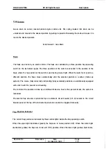
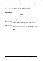
7.1 1 . ELECTRICAL SYSTEM
Schematic (simplified):
ELECTRICAL SHELF
ON ENGINE
HOIJN'l'
HP2400_01
ENGlllE
FLIGHT
r - - - - - - - - - - -I
•
I
VOLTAGE
� �
,S �
I
I
REGUIATOR
B
�
R'o
0
VR24JO_Ol
a " 101
.. ,.
!
N
0
;:; ;:;
P24JO-Ol
P/.J2400-01
LO
\;OLTf,GE;
CAl1!ION LIGHT
052430-02
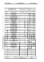
Description
I
GEtl2 4JO-Ol
!
C
GENERATOR
CB24JO-OI
GENERATOR
aBOIO-OI
ENGINE
S'l'AA';E:R
I
I
OVERVOLTAGE
COh"TROL RELAY
1
K14JO-Ol
STARTING
- C24JO-Ol
�
I
SA�!
I
><AS"""
RELAY
I
I
I
I
KaOIO-Ol
I
I
I F
- -
- -
-
-
- - -
11
BATTER!
12V/JOJUl
0
B'l'2431-01
,
,
,
F
GEHERA'1OR WARN LlGHT
052430-01
52400_01
OVERVOLTAGE
:
e:"xn:RY
,
HAS"'"
SENSOR
SHITCH
SE 2430_01
SENSING
CON'IROL
-01
57t.:JO-Ol
S!AJI.'l'ING SWITCH
PART OF
WGNITIOIl
SHIl'Cil
�
U/GlNE
STAAT
CSBOIO-C!
GENEAATOR
CONTROL
CB2430-02
•
R
�
52450-01
AVIOt1ICS
HASn:R
SHITCH
R
•
Power
The battery is connected to the master bus via the master circuit breaker (50 Amps). The generator
which is integrated in the engine recharges the battery via the generator circuit breaker (25 Amps).
Both circuit breakers can be triggered manually. The generator warning light is fed by the voltage
regulator and illuminates when the generator is not charging the battery,
The engine is provided with two independent ignition systems. The two magnetos are independent
from the rest of the electrical power system, and are in operation as soon as the engine is running.
This ensures safe engine operation even in case of an electrical power failure.
Revision No.
WARNING
If the ignition key is turned to L. R or BOTH. the respective magneto is "hot". If the
propeller is moved during this time the engine may fire and cause serious or fatal injury
to personnel.
Reference
Date
October 20, 1 993
Page
7
-
1 4