


Intesis
TM
Modbus Server
– HITACHI VRF
User Manual r1.0 EN
© HMS Industrial Networks S.L.U - All rights reserved
This information is subject to change without notice
URL
http
s
://www.intesis.com
22 / 30
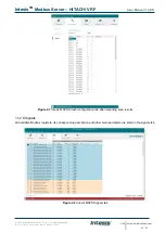
Figure 4.10
Diagnostic
More information about the Diagnostic section can be found in the Configuraion Tool manual.
1.12.9 Set-up procedure
1. Install Intesis MAPS on your laptop, use the setup program supplied for this and follow the instructions given by
the Installation wizard.
2. Install Intesis in the desired installation site. Installation can be on DIN rail or on a stable not vibrating surface
(DIN rail mounted inside a metallic industrial cabinet connected to ground is recommended).
3. If using Modbus RTU, connect the communication cable coming from the EIA485 port of the Modbus RTU
installation to the port marked as Port B of Intesis (More details in section 3).
If using, Modbus TCP, connect the communication cable coming from the Ethernet port of the Modbus TCP
installation to the port marked as Ethernet Port of Intesis (More details in section 3).
4. Connect the communication cable coming from the Hitachi VRF installation to the port marked as Port A of
Intesis (More details in section 3).
5. Power up Intesis. The supply voltage can be 9 to 36 Vdc or just 24 Vac. Take care of the polarity of the supply
voltage applied.
WARNING!
In order to avoid earth loops that can damage Intesis and/or any other equipment connected to
it, we strongly recommend:
•
The use of DC power supplies, floating or with the negative terminal connected to earth.
Never use a
DC power supply with the positive terminal connected to earth
.
•
The use of AC power supplies only if they are floating and not powering any other device.


