


5. Installation
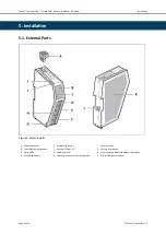
5.1. External Parts
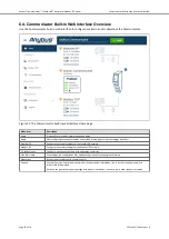
Figure 3. External parts
A. Power connector
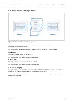
B. Label with LED designation
C. Status LEDs
D. Configuration port
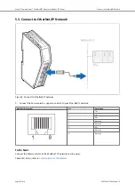
E. EtherNet/IP port x 2
F. Modbus TCP port x 2
G. Cable tie mount
H. Laser engraved connectors designation
I.
Security switch
J. Factory reset button
K. Laser engraved label with product information
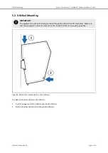
L. DIN rail locking mechanism
Anybus
®
Communicator
™
- EtherNet/IP
™
Adapter to Modbus TCP Server
Installation
Page 8 of 56
SCM-1202-196 Version 1.0