


FIRNET Controller 1.0
7.4.2
Scenes - Loading and Saving
Previously Stored Settings
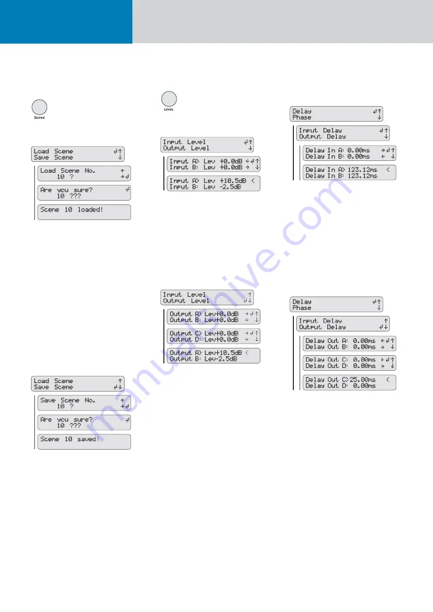
Load Scene - Accessing Previously Stored Settings
To load previously created and stored scenes, press
the SCENE key and then the
RS
keys to select the
menu option Load Scene, if not already selected.
Press the ENTER key to go to the Load Scene
submenu and the
QP
keys to choose the number
of the desired scene from 0 to 9. Press the ENTER
key to load the selected scene. The LCD will issue
a warning reading Different Speaker Series if the
selected scene uses speaker-specifi c fi lter sets other
than those used by the current scene. You must
confi rm by pressing the ENTER key. A confi rmation
prompt then appears in the LCD asking Are you
sure? Confi rm again by pressing the ENTER key.
Scene X appears in the LCD indicating the given
scene has been loaded.
Save Scene - Storing Settings as a Scene
Once you have confi gured the controller to suit the
venue, you can store the FIRNET’s current setup as
a scene. To do this, press the SCENE key and then
the
RS
keys to choose the menu option Save
Scene (press the
S
key once). Press the ENTER key
to go to the Save Scene No submenu and the
QP
arrow keys to choose a number from 0 to 9 for the
memory slot in which you wish to store the scene.
Press the ENTER key again to save the scene to the
chosen memory slot. A confi rmation prompt then
appears in the LCD asking Are you sure? Confi rm
again by pressing the ENTER key. Scene X appears
in the LCD indicating you have saved the scene.
7.4.3 Adjusting Levels
Adjusting Input Levels
To adjust the signal levels at the FIRNET’s inputs,
press the LEVEL key and then the
RS
keys to
select the menu option Input Level, if not already
selected. After pressing the ENTER key, use the
RS
keys to select an audio input (Input A or
Input B) and the
QP
keys to set the desired gain
for this input. Then press the ENTER key to confi rm
and assign this level.
Adjusting Output Levels
To adjust signal levels at the FIRNET’s outputs,
press the LEVEL key and then the
RS
keys to
select the menu option Output Level (press the
S
key once). After pressing the ENTER key, use the
arrow
RS
keys to select an audio output (Output
A to Output D) and the
QP
keys to set the desired
gain for this output. Then press the ENTER key to
confi rm and assign this level.
7.4.4 Delay/Phase
Adjusting Input Delays
To adjust the delays at the FIRNET’s inputs, press
the DELAY/PHASE key and then the arrow up and
down keys to select the menu option Delay, if not
already selected. Press the ENTER key and then the
RS
keys to select the menu option Input Delay, if
not already selected. After pressing the ENTER key,
use the
RS
keys to select an audio input (Input
A or Input B) and the
QP
keys to set the desired
delay within a range of 0 to 500 ms for this input.
Then press the ENTER key to confi rm and assign
this delay setting
Adjusting Output Delays
To adjust the delays at the FIRNET’s outputs, press
the DELAY/PHASE key and then the
RS
keys
to select the menu option Delay, if not already
selected. Press the ENTER key and then the
RS
keys to select the menu option Output Delay (press
S
once). After pressing the ENTER key, use the
RS
keys to select an audio output (Output A to
Output D) and the
QP
keys to set the desired
delay within a range of 0 to 500 ms for this output.
Then press the ENTER key to confi rm and assign
this delay setting.