background image

BSW


FAN-COIL HIGH PRESSURE


06.18 Ref. 207483 Rev.102


9


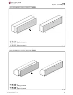
PAM (SUPPLY PLENUM) ASSEMBLY DIAGRAM


PAM (INTAKE PLENUM) ASSEMBLY DIAGRAM


SCREWS LEGEND PAM 1÷5 

x8 Screw TC+M5x12 UNI7687 

x6 Hex nut M5 flanged with corrugated washer DIN4161 


SCREWS LEGEND PAM 6÷7 

x10 Screw TC+M5x12 UNI7687 

x6 Hex nut M5 flangiato with corrugated washer DIN4161 

Pic. 07 

Summary of Contents for BSW 1

Page 1: ...Rev 102 1 BSW Cooling only FAN COIL HIGH PRESSURE Models 1 2 3 4 5 6 7 Cooling capacities from 3 8 to 50 6 kW Heating capacities from 5 0 to 60 9 kW 06 18 Ref 207483 Rev 102 INSTALLATION OPERATION AND MAINTENANCE MANUAL ...

Page 2: ...BSW FAN COIL HIGH PRESSURE 2 06 18 Ref 207483 Rev 102 ...

Page 3: ...LY DIAGRAM 10 PAM MOUNTING BRACKET ASSEMBLY DIAGRAM 11 RAM MOUNTING BRACKET ASSEMBLY DIAGRAM 11 GAM ASSEMBLY DIAGRAM 12 SRE ASSEMBLY DIAGRAM 12 SRA ASSEMBLY DIAGRAM 13 USG ASSEMBLY DIAGRAM 13 SSP ASSEMBLY DIAGRAM 14 ALUMINIUM DAMPER ASSEMBLY DIAGRAM 14 BAM ON PAN ASSEMBLY DIAGRAM 15 BAM ON RAM ASSEMBLY DIAGRAM 15 SUPPLY GRILL ON PAM ASSEMBLY DIAGRAM 16 SUPPLY GRILL ON RAM ASSEMBLY DIAGRAM 16 INTAK...

Page 4: ...ed for long periods make sure that the controls are in the position 0 off If the unit is not going to be used in winter when temperatures are near to freezing drain the system and ensure that the unit heat exchanger has no water in it in order to prevent the formation of ice and consequent breakage To make the unit inoperable disconnect it totally from the electricity supply It is unsafe to alter ...

Page 5: ... 656 956 1156 1306 1406 B mm 253 253 303 328 353 M mm 680 980 1180 1330 1430 C mm 247 247 297 322 347 D mm 237 237 237 300 5 300 5 E mm 118 118 118 195 195 F mm 93 5 93 5 118 5 131 143 5 G mm 233 233 233 310 310 I mm 83 5 83 5 108 5 121 133 5 N mm 193 193 193 270 270 Fittings male 2 rows coil Ø 1 2 1 2 3 4 3 4 1 4 rows coil Ø 1 2 3 4 3 4 1 1 6 rows coil Ø 3 4 3 4 1 1 1 1 4 Net weight kg 28 38 49 6...

Page 6: ...7 MOD 6 7 L mm 2190 2190 H mm 373 398 P mm 770 770 A mm 2076 2076 B mm 328 353 M mm 2100 2100 C mm 323 348 D mm 300 5 300 5 E mm 201 5 201 5 F mm 131 5 144 G mm 311 311 I mm 121 5 134 N mm 270 270 Fittings male 2 rows coil Ø 1 1 4 rows coil Ø 1 1 4 1 1 2 6 rows coil Ø 1 1 2 1 1 2 Net weight kg 127 Pic 02 ...

Page 7: ...ply line Drill the holes in line with the relative slots for the 6 unit screw anchors Pic 4 Inject thermosetting resin into the holes and then insert the screw anchors Pic 5 Fix the threaded rods of the correct length to the screw anchors Pic 5 and insert them into the relative slots Pic 6 After having created a slope max 3 cm m in the direction of the condensate outlet lock the threaded rod with ...

Page 8: ...8 Ref 207483 Rev 102 EXAMPLE OF ACCESSORIES USE AND COMPATIBILITY UNIT PAM RAM GAM SRE SRA USG SSP Aluminium damper BAM Air intake grill Air supply grill Depending on the requirements the air filter can have a thickness of 12 25 48 mm ...

Page 9: ...LENUM ASSEMBLYDIAGRAM PAM INTAKEPLENUM ASSEMBLYDIAGRAM SCREWS LEGEND PAM 1 5 x8 Screw TC M5x12 UNI7687 x6 Hex nut M5 flanged with corrugated washer DIN4161 SCREWS LEGEND PAM 6 7 x10 Screw TC M5x12 UNI7687 x6 Hex nut M5 flangiato with corrugated washer DIN4161 Pic 07 ...

Page 10: ...TE M5x12 UNI 5739 TE M5x12 SCREWS LEGEND RAM 6 7 x6 Screw TC M5x12 UNI7687 x6 Hex nut M5 flanged with corrugated washer DIN4161 x4 Screw TE M5x12 UNI 5739 Pic 09 SCREWS LEGEND RAM 1 5 x7 Screw TC M5x12 UNI7687 TE M5x12 x6 Hex nut M5 flanged with corrugated washer DIN4161 x1 Screw TE M5x12 UNI 5739 SCREWS LEGEND RAM 6 7 x8 Screw TC M5x12 UNI7687 x6 Hex nut M5 flanged with corrugated washer DIN4161 ...

Page 11: ... 207483 Rev 102 11 PAMMOUNTINGBRACKETASSEMBLYDIAGRAM RAMMOUNTINGBRACKETASSEMBLYDIAGRAM SCREWS LEGEND 1 5 x6 Self drilling screw with tip TC 3 9x9 5 UNI6954 Pic 11 SCREWS LEGEND 1 5 x6 Self drilling screw with tip TC 3 9x9 5 UNI6954 Pic 12 ...

Page 12: ... 102 GAMASSEMBLYDIAGRAM SREASSEMBLYDIAGRAM SCREWS LEGEND SRE 1 5 x8 Screw TC M5x12 UNI7687 x6 Hex nut M5 flanged with corrugated washer DIN4161 SCREWS LEGEND SRE 6 7 x10 Screw TC M5x12 UNI7687 x6 Hex nut M5 flanged with corrugated washer DIN4161 Pic 14 ...

Page 13: ...2 13 SRAASSEMBLYDIAGRAM USGASSEMBLYDIAGRAM SCREWS LEGEND SRA 1 5 x8 Screw TC M5x12 UNI7687 x6 Hex nut M5 flanged with corrugated washer DIN4161 SCREWS LEGEND SRA 6 7 x10 Screw TC M5x12 UNI7687 x6 Hex nut M5 flanged with corrugated washer DIN4161 Pic 15 ...

Page 14: ...AGRAM CANALIZABLE SIDE Lined up to the edge SCREWS LEGEND SSP 1 5 x8 Screw TC M5x12 UNI7687 x6 Hex nut M5 flanged with corrugated washer DIN4161 UNIT ACCESSORIES SIDE Shorter to mix the air flow SCREWS LEGEND SSP 6 7 x10 Screw TC M5x12 UNI7687 x6 Hex nut M5 flanged with corrugated washer DIN4161 Pic 17 ...

Page 15: ... BAM ON PANASSEMBLYDIAGRAM BAM ON RAMASSEMBLYDIAGRAM SCREWS LEGEND 1 5 x8 Screw TC M5x12 UNI7687 x8 Hex nut M5 flanged with corrugated washer DIN4161 SCREWS LEGEND 6 7 x10 Screw TC M5x12 UNI7687 x10 Hex nut M5 flanged with corrugated washer DIN4161 Pic 19 ...

Page 16: ...RAM SUPPLYGRILLON RAMASSEMBLYDIAGRAM SCREWS LEGEND 1 5 x6 Self drilling screw TC 4 2x13 UNI8118 SCREWS LEGEND 6 7 x8 Self drilling screw TC 4 2x13 UNI8118 Pic 21 SCREWS LEGEND 1 5 x6 Self drilling screw TC 4 2x13 UNI8118 SCREWS LEGEND 6 7 x8 Self drilling screw TC 4 2x13 UNI8118 Pic 22 ...

Page 17: ...RAM INTAKE GRILL ON RAMASSEMBLYDIAGRAM SCREWS LEGEND 1 5 x6 Self drilling screw TC 4 2x13 UNI8118 SCREWS LEGEND 6 7 x8 Self drilling screw TC 4 2x13 UNI8118 Pic 23 SCREWS LEGEND 1 5 x6 Self drilling screw TC 4 2x13 UNI8118 SCREWS LEGEND 6 7 x8 Self drilling screw TC 4 2x13 UNI8118 Pic 24 ...

Page 18: ... of the water in the trap Upon completion of work check that the condensate flows out properly by pouring water into the tray The condensate water drainage system should be fabricated in a workmanlike manner and should be periodicallychecked The manufacturer cannot be held liable for any damage caused by dripping in the absence of a valve or of periodic maintenance of the drainage system ELECTRICA...

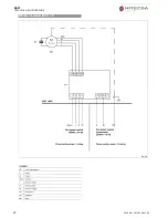
Page 19: ...BSW FAN COIL HIGH PRESSURE 06 18 Ref 207483 Rev 102 19 WIRING DIAGRAM MOD 1 3 ...

Page 20: ...BSW FAN COIL HIGH PRESSURE 20 06 18 Ref 207483 Rev 102 WIRING DIAGRAM MOD 4 5 ...

Page 21: ...BSW FAN COIL HIGH PRESSURE 06 18 Ref 207483 Rev 102 21 WIRING DIAGRAM MOD 6 7 ...

Page 22: ...ND MAINTENANCE CAUTION Before carrying out any cleaning or maintenance work disconnect the unit from the mains electricity supply ROUTINE MAINTENANCE The user is duty bound to have all maintenance operations carried out by trai ned and qualified personnel only If the unit has to be dismantled protect hands with work gloves Monthly checks Ensure that the fan impellers are clean If they are dirty cl...

Page 23: ...as before Check that the filter and the coil are clean no air has entered the water circuit by bleeding from the relative valve the installation is correctly balanced the boiler chiller is in proper working order DISMANTLING THE UNIT This unit is made to last for many years Qualified personnel are needed to dismantle it in all safety The first operation to be carried out before dismantling the uni...

Page 24: ...BSW FAN COIL HIGH PRESSURE 24 06 18 Ref 207483 Rev 102 NOTES ...

Page 25: ... 18 Ref 207483 Rev 102 25 HIPLUS AIRE ACONDICIONADO S L Masia Torrents 2 Tel 34 93 893 49 12 Fax 34 93 893 96 15 08800 Vilanova i la Geltrú Barcelona Spain www hitecsa com We reserve the right to change specification without notice ...

Reviews: