-27-
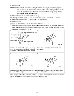
(2) Removal of Front Cap (F)
[5] <1>
and Protector (J)
[6] <2>
Insert a small flat-blade screwdriver between Front Cap (F)
[5] <1>
and Protector (J)
[6] <2>
and remove them from the Hammer Case
[7] <3>
.
(3) Removal of Hook (A)
[41] <38>
Remove the M4 Truss Hd. Screw (Black)
[42] <38>
and Hook (A)
[41] <38>
. By removing
Hook (A)
[41] <38>
, disassembly can be done easily.
(4) Removal of the Carbon Brushes 5 x 6 x 11.5
[32] <29>
Remove the two Brush Caps
[33] <30>
. Catch the flanges of the Carbon Brushes 5 x 6 x 11.5
[32] <29>
with a small flat-blade screwdriver and remove the Carbon Brushes 5 x 6 x 11.5
[32] <29>
at both sides.
(5) Removal of housing (B)
Remove the nine Tapping Screws (W/Flange) D4 x 20 (Black)
[34] <31>
from the main body.
The Strap (Black)
[49] <45>
can be removed by removing the Tapping Screw (W/Flange) D4 x
20 (Black)
[34] <31>
. Before removing housing (B), be sure to remove the Brush Caps
[33]
<30>
because housing (B) cannot be removed if the Brush Caps
[33] <30>
are mounted.
(6) Removal of the switch
The FET of the DC-Speed Control Switch
[45] <42>
is firmly inserted in the housing.
Insert a small flat-blade screwdriver between the FET and housing (B) to raise and remove
the FET. Then, Hammer Case
[7] <3>
, hammer assembly, Inner Cover (D)
[25] <22>
,
Armature Ass’y DC 14.4V
[26] <23>
, Magnet (D)
[28] <25>
, Brush Block
[31] <28>
, DC-
Speed Control Switch
[45] <42>
, Controller
[46] <43>
, terminal support and LED light can be
removed in a piece. Pushing Button (A)
[38] <35>
can also be removed.
NOTE: Be careful not to break the three legs coming from the FET to avoid malfunction
of the switch.


