background image

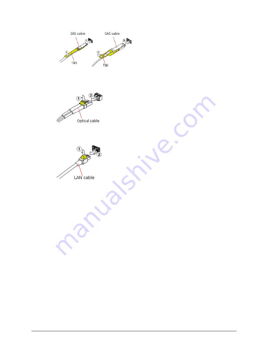
To remove an optical cable, push the top of the connector of the optical cable (1) to release
the latch and remove the SAS cable (2).

To remove a LAN cable, push the top of the LAN cable connector (1) to release the latch and
remove the LAN cable (2).

Removing cables

Chapter 6: Maintaining the storage system

VSP N400, N600 Hardware Reference Guide

60

Summary of Contents for VSP N400

Page 1: ...m N400 N600 83 06 0x Hardware Reference Guide This document provides information about the system hardware components mechanical and environmental specifications for the VSP N400 and VSP N600 storage systems MK 94HM8053 02 March 2021 ...

Page 2: ...a continues to be held retrieved deleted or otherwise processed in accordance with relevant laws Notice on Export Controls The technical data and technology inherent in this Document may be subject to U S export control laws including the U S Export Administration Act and its associated regulations and may be subject to export or import regulations in other countries Reader agrees to comply strict...

Page 3: ...ity 20 Examples of supported VSP N400 configurations 20 Examples of supported VSP N600 configurations 20 Maximum number of mounted drive trays 21 Chapter 2 Virtual Storage Platform N400 N600 controller 24 CBLM controller 24 CBLM with front panel bezel 24 CBLM front panel LEDs without bezel 25 CBLM rear panel 27 CBLM power supply unit LEDs and connectors 29 Host Network and Drive Tray Ports and LED...

Page 4: ...d connectors 42 Flash module drive tray DBF 42 FMD with front panel bezel 43 FMD front panel without bezel 44 FMD rear panel 45 High density intermix drive tray DB60 46 Dense intermix drive tray with front panel bezel 47 Dense intermix drive tray display LEDs 48 Dense intermix drive tray rear panel 49 Chapter 4 Host port expansion chassis 51 Host port expansion chassis front panel bezel LEDs 51 PC...

Page 5: ...dix F Data and power cables 84 Required cables 84 Fibre Channel cables 86 iSCSI cables 89 iSCSI standards 91 iSCSI specifications 92 Managing cables 95 AC power cables 97 Power cable assemblies 98 AC connections 99 Power cable usage guidelines 101 Three phase power considerations for racks 102 Cable management 102 Appendix G Port address mapping 103 Port address mapping 103 Appendix H Non Hitachi ...

Page 6: ...Appendix I Regulatory compliance 108 Appendix J Environmental notices 110 Index 111 Contents VSP N400 N600 Hardware Reference Guide 6 ...

Page 7: ...nformation see the UEFI Development Kit website http sourceforge net apps mediawiki tianocore index php title UDK2010 2004 Intel Corporation All rights reserved Redistribution and use in source and binary forms with or without modification are permitted provided that the following conditions are met Redistributions of source code must retain the above copyright notice this list of conditions and t...

Page 8: ...ersion This document revision applies to the following product versions VSP N400 N600 firmware 83 06 0x or later Hitachi Storage Virtualization Operating System SVOS 7 4 1 or later Hitachi NAS firmware version 13 2 or later Release notes Read the release notes before installing and using this product They may contain requirements or restrictions that are not fully described in this document or upd...

Page 9: ...ckets Indicates optional values Example a b indicates that you can choose a b or nothing braces Indicates required or expected values Example a b indicates that you must choose either a or b vertical bar Indicates that you have a choice between two or more options or arguments Examples a b indicates that you can choose a b or nothing a b indicates that you must choose either a or b This document u...

Page 10: ...or 1 0003 bytes 1 terabyte TB 1 000 GB or 1 0004 bytes 1 petabyte PB 1 000 TB or 1 0005 bytes 1 exabyte EB 1 000 PB or 1 0006 bytes Logical capacity values for example logical device capacity cache memory capacity are calculated based on the following values Logical capacity unit Value 1 block 512 bytes 1 cylinder Mainframe 870 KB Open systems OPEN V 960 KB Others 720 KB 1 KB 1 024 210 bytes 1 MB ...

Page 11: ...act information https support hitachivantara com en_us contact us html Hitachi Vantara Community is a global online community for Hitachi Vantara customers partners independent software vendors employees and prospects It is the destination to get answers discover insights and make connections Join the conversation today Go to community hitachivantara com register and complete your profile Comments...

Page 12: ... protocols All storage system models allow defective drives to be replaced without the interruption of data availability to hosts A hot spare drive can be configured to replace a failed drive automatically securing the fault tolerant integrity of the logical drives Self contained hardware based RAID logical drives provide maximum performance in compact external enclosures Essential hardware compon...

Page 13: ...onsist of 10 Gbps iSCSI 28 ports per system or 32 ports per systems for systems without drives or 12 ports per systems when NAS Modules are installed 10 Gbps iSCSI Copper 28 ports per system or 32 ports per systems for systems without drives or 12 ports per systems when NAS Modules are installed 8 Gbps Fibre Channel 56 ports per system or 64 ports per systems for systems without drives or 24 ports...

Page 14: ...W F800 DBSC Silver rated power supply DW F800 DBSE Platinum rated power supply 2 5 inch SFF 24 2U 86 2 mm LFF drive tray DW F800 DBL power supply contains BNST DW F800 DBLC Silver rated power supply DW F800 DBLE Platinum rated power supply 3 5 inch LFF 12 2U 86 2 mm FMD tray DW F800 DBF 5 25 inch FMD 12 2U 86 2 mm VSP N400 model Chapter 1 Hitachi Virtual Storage Platform N400 N600 hardware overvie...

Page 15: ... LFF disk drive 1 2 TB DKC F810I 2R4JGM SFF disk drive 2 4 TB DKC F810I 2R4J8M LFF disk drive 2 4 TB DKC F810I 6R0H9M LFF disk drive 6 TB DKC F810I 10RH9M LFF disk drive 10 TB Flash module drives The VSP N400 storage system supports the listed flash module drive capacities Model number Drive type Drive capacity DKC F810I 7R0FP FMD 7 TB DKC F810I 14RFP FMD 14 TB Solid state drives The VSP N400 stor...

Page 16: ...ystems when NAS Modules are installed 10 Gbps iSCSI Copper 28 ports per system or 32 ports per systems for systems without drives or 12 ports per systems when NAS Modules are installed 8 Gbps Fibre Channel 56 ports per system or 64 ports per systems for systems without drives or 24 ports per systems when NAS Modules are installed 16 Gbps Fibre Channel 2 port 28 ports per system or 32 ports per sys...

Page 17: ...W F800 DBSC Silver rated power supply DW F800 DBSE Platinum rated power supply 2 5 inch SFF 24 2U 86 2 mm LFF drive tray DW F800 DBL power supply contains BNST DW F800 DBLC Silver rated power supply DW F800 DBLE Platinum rated power supply 3 5 inch LFF 12 2U 86 2 mm FMD tray DW F800 DBF 5 25 inch FMD 12 2U 86 2 mm VSP N600 model Chapter 1 Hitachi Virtual Storage Platform N400 N600 hardware overvie...

Page 18: ... TB DKC F810I 1R2J5M LFF disk drive 1 2 TB DKC F810I 2R4JGM SFF disk drive 2 4 TB DKC F810I 2R4J8M LFF disk drive 2 4 TB DKC F810I 6R0H9M LFF disk drive 6 TB DKC F810I 10RH9M LFF disk drive 10 TB Flash module drives The VSP N600 storage system supports the listed flash module drive capacities Model number Drive type Drive capacity DKC F810I 7R0FP FMD 7 TB DKC F810I 14RFP FMD 14 TB Solid state driv...

Page 19: ...s of other Storage Systems Maximum number of volumes per RAID group 2 048 Maximum number of DP pool volumes 4 096 Maximum number of DP pools 64 Maximum number of iSCSI hosts connected through a network switch 255 Maximum number of Fibre Channel devices connected through a Fibre Channel switch 255 Maximum storage system capacity physical capacity Using 2 4 TB HDD VSP N400 885 TB VSP N600 1 328 TB U...

Page 20: ...2 Hitachi Accelerated Flash HAF flash module drives Dense intermix drive tray 8 Note If a drive is inserted into a slot of a dense intermix drive tray when the installed number of drives exceeds 240 slots per path the drive is blocked Examples of supported VSP N600 configurations The following table lists the maximum number of drive trays and drives supported in a system configuration A diskless c...

Page 21: ... blocked Maximum number of mounted drive trays The following table lists the maximum number of mountable drive trays and mountable drives for each drive type Note If a drive is inserted into a slot of a dense intermix drive tray when the installed number of drives exceeds 240 slots per path the drive is blocked Maximum number of mounted drive trays Chapter 1 Hitachi Virtual Storage Platform N400 N...

Page 22: ...Ds or SSDs FMD 24 288 FMDs HAF Dense intermix drive tray 12 720 HDDs or SSDs1 Note 1The following SSD capacities 200 GB and 400 GB are supported in a dense intermix drive tray VSP N400 controller Number of mounted drive trays Maximum 12 per path Maximum number of mounted drives SFF LFF drives Dense intermix drive tray SFF drive dense intermix drive tray LFF drive dense intermix drive tray CBLM 16 ...

Page 23: ...e trays Maximum 12 per path Maximum number of mounted drives SFF LFF drives Dense intermix drive tray SFF drive dense intermix drive tray LFF drive dense intermix drive tray CBLM 24 0 576 288 21 1 564 312 20 2 600 360 17 3 588 384 16 4 624 432 13 5 612 456 12 6 648 504 9 7 636 528 8 8 672 576 5 9 660 600 4 10 696 648 1 11 684 672 0 12 720 720 Maximum number of mounted drive trays Chapter 1 Hitachi...

Page 24: ...in available to data hosts using a redundant data path through the other controller The controller is equipped with LED indicators for monitoring its operating conditions and notifying possible component replacement CBLM controller The CBLM controller includes specific functional LEDs located on the front and rear of controller and power supplies to provide its operating status CBLM with front pan...

Page 25: ... assistance contact customer support https support hitachivantara com en_us contact us html 5 POWER ON OFF main switch Powers the storage system 6 Lock Locks and unlocks the front panel bezel by using the supplied key Note Removing a controller can cause the POWER READY WARNING and ALARM LEDs on the front panel to turn off These LEDs return to the on status after the storage system recovers from t...

Page 26: ...ntrollers Controller 1 bottom and Controller 2 top 4 Backup module N A 5 BACKUP STTS LED Green Power restoration in progress following power outage Fast blink green Restoring Slow blink green Restoring or sequential shutdown in progress 6 Cache flash memory N A 7 ALM LED for cache flash memory Red Cache flash memory can be removed 8 CTL ALM LED Red Controller can be removed CBLM front panel LEDs w...

Page 27: ...e Blink red two times Backup battery failure Blink red three times Both batteries failed or preventive maintenance replacement of batteries can run Off Battery is not mounted battery mounting failure occurred or firmware is being upgraded Off is normal status for configurations without batteries for example BKMF 10 and BKMF 20 CBLM rear panel The following table describes the definitions of the CB...

Page 28: ...1 Power supply unit 2 Front end module 3 Back end module 4 LAN blade Rear view includes NAS modules CBLM rear panel Chapter 2 Virtual Storage Platform N400 N600 controller VSP N400 N600 Hardware Reference Guide 28 ...

Page 29: ...ed 2 Receptacle Connects to the power cable provided with the storage system 3 RDY LED Green Normal operation Host Network and Drive Tray Ports and LEDs The controllers are equipped with specific interfaces for connecting powering configuring and managing the storage system The component LEDs display the operating status of the storage system Front end modules CBLM power supply unit LEDs and conne...

Page 30: ...US LED Green Front end module is in the power on state Red Front end module can be removed safely 2 PORT LED Red Small form factor pluggable can be removed Blue Normal link status at 16 Gbps Green Normal link status at 4 Gbps or 8 Gbps 3 Fibre Channel connectors Connect to Fibre Channel cables 10 Gbps iSCSI board LEDs and connectors optical Chapter 2 Virtual Storage Platform N400 N600 controller V...

Page 31: ...C CHB 1D 1D 3D CHB 1E 1E 3E CHB 1F 1F 3F CHB 1G 1G 3G CHB 1H 1H 3H CHB 2A 2A 4A CHB 2B 2B 4B CHB 2C 2C 4C CHB 2D 2D 4D CHB 2E 2E 4E CHB 2F 2F 4F CHB 2G 2G 4G CHB 2H 2H 4H 16 Gbps Fibre Channel 2 port board LEDs and connectors Chapter 2 Virtual Storage Platform N400 N600 controller VSP N400 N600 Hardware Reference Guide 31 ...

Page 32: ...sferred 3 LAN 2 LAN port used by the user 4 LAN 1 Maintenance LAN port used by service personnel 5 LAN ALARM LED Red LAN blade can be removed 6 Uninterruptible power supply UPS port N A Back end modules LAN blade LEDs and connectors Chapter 2 Virtual Storage Platform N400 N600 controller VSP N400 N600 Hardware Reference Guide 32 ...

Page 33: ...e Red Back end module can be removed safely 2 PORT LED Blue Link status is normal 3 PATH 0 connector Connect to a drive tray 4 PATH 1 connector Connects to a drive tray Back end modules Chapter 2 Virtual Storage Platform N400 N600 controller VSP N400 N600 Hardware Reference Guide 33 ...

Page 34: ...host connection ports conventional hard disk drives HDD are not included or configurable with all flash arrays Small form factor drive tray DBS DBSE The following describes the physical specifications of the small form factor drive tray Name Model name Height Number of drive slots Drive type DBS DW F800 DBSC 2U 88 2 mm 24 2 5 inch SFF DBSE DW F800 DBSE 2U 88 2 mm 24 2 5 inch SFF SFF with front pan...

Page 35: ...el without bezel Number Item Description 1 POWER READY and LOCATE LEDs Green Drive tray is powered on Green Drive tray is operational Amber Indicates the location of the chassis Can be turned on or turned off by the maintenance utility 2 ALM LED Red Drive stopped due to a failure and can be replaced 3 ACT LED Green Normal operation SFF front panel without bezel Chapter 3 Drive trays VSP N400 N600 ...

Page 36: ... Number Item Description 1 ENC N A 2 POWER LED Green ENC is in the power on state 3 Locate LED Amber Indicates the location of the chassis Can be turned on or turned off by the maintenance utility 4 ALARM LED Red ENC can be replaced 5 PATH IN LED Blue IN side port is linked up 6 PATH IN connector Connects to a controller or drive tray SFF rear panel Chapter 3 Drive trays VSP N400 N600 Hardware Ref...

Page 37: ...l operation SFF and LFF AC power supply unit LEDs and connectors Both SFF and LFF drive trays are equipped with AC power supply units The AC power supply units include LEDs to display its operating status Note The DBS and DBL power supply has a Silver efficiency rating The DBSE and DBLE power supply has a Platinum efficiency rating Number Item Description 1 RDY LED Green Normal operation 2 ACI IN ...

Page 38: ...en Normal operation 2 DC IN LED Green DC input is operating normally 3 ALM LED Red Power supply unit can be replaced Large form factor drive tray DBL DBLE The following describes the physical specifications of the large form factor drive tray Name Model name Height Number of drive slots Drive type DBL DW F800 DBLC 2U 88 2 mm 12 3 5 inch LFF DBLE DW F800 DBLE 2U 88 2 mm 12 3 5 inch LFF SFF power su...

Page 39: ...s the location of the chassis Can be turned on or turned off by the maintenance utility 4 Lock Locks and unlocks the front panel bezel by using the supplied key LFF front panel without bezel Number Item Description 1 POWER READY and LOCATE LEDs Green Drive tray is powered on LFF with front panel bezel Chapter 3 Drive trays VSP N400 N600 Hardware Reference Guide 39 ...

Page 40: ...ccessed 3 ALM LED Red Drive stopped due to a failure and can be replaced 4 Large form factor drives The twelve 3 5 inch large form factor drives are positioned horizontally The slots are organized in the following order 8 9 10 11 4 5 6 7 0 1 2 3 LFF rear panel Number Item Description 1 ENC N A 2 POWER LED Green ENC is in the power on state LFF rear panel Chapter 3 Drive trays VSP N400 N600 Hardwar...

Page 41: ...1 Receptacle Connects to the power cable provided with the storage system 12 AC IN LED Green Normal operation 13 ALM LED Red Power supply unit can be replaced 14 RDY LED Green Normal operation SFF and LFF AC power supply unit LEDs and connectors Both SFF and LFF drive trays are equipped with AC power supply units The AC power supply units include LEDs to display its operating status Note The DBS a...

Page 42: ...supply units The DC power supply units include LEDs to display its operating status Number Item Description 1 RDY LED Green Normal operation 2 DC IN LED Green DC input is operating normally 3 ALM LED Red Power supply unit can be replaced Flash module drive tray DBF The following describes the physical specifications of the flash module drive tray SFF power supply unit LEDs and connectors Chapter 3...

Page 43: ...OWER LED Green Drive tray is powered on 2 READY LED Green Drive tray is operational 3 Locate LED Amber Indicates the location of the chassis Can be turned on or turned off by the maintenance utility 4 Lock Locks and unlocks the front panel bezel by using the supplied key FMD with front panel bezel Chapter 3 Drive trays VSP N400 N600 Hardware Reference Guide 43 ...

Page 44: ...the LED blinks for about two to five minutes until the startup processing is complete ALM LED Red Drive stopped due to a failure and can be replaced Note ACT indicator is only printed on some types of FMDs 3 POWER READY and LOCATE LEDs Green Drive tray is powered on Green Drive tray is operational FMD front panel without bezel Chapter 3 Drive trays VSP N400 N600 Hardware Reference Guide 44 ...

Page 45: ...dule drives Slots are organized the following way 9 10 11 6 7 8 3 4 5 0 1 2 FMD rear panel Number Item Description 1 ENC N A 2 POWER LED Green ENC is in the power on state 3 Locate LED Amber Indicates the location of the chassis Can be turned on or turned off by the maintenance utility FMD rear panel Chapter 3 Drive trays VSP N400 N600 Hardware Reference Guide 45 ...

Page 46: ... with the storage system 11 Three LEDS top to bottom RDY LED AC IN LED ALM REPLACE LED Green Power supply unit is operating normally Green Power supply unit is operating normally Red Power supply unit can be replaced High density intermix drive tray DB60 The following describes the physical specifications of the high density drive tray Name Model name Height Number of drive slots Drive type DB60 D...

Page 47: ...reen Drive tray is operational 3 Locate LED Amber Indicates the location of the chassis Can be turned on or turned off by the maintenance utility 4 Lock Locks and unlocks the front panel bezel by using the supplied key Dense intermix drive tray with front panel bezel Chapter 3 Drive trays VSP N400 N600 Hardware Reference Guide 47 ...

Page 48: ...failure and can be replaced Note At the rear of the drive tray the drives are organized from left to right On the left side of the preceding figure the rear of the drive tray is at the top Rear of drive tray 48 59 36 47 24 35 12 23 Front of drive tray 00 11 Dense intermix drive tray display LEDs Chapter 3 Drive trays VSP N400 N600 Hardware Reference Guide 48 ...

Page 49: ...the power cable provided with the storage system 6 ENC N A 7 PATH OUT LED Blue OUT side port is linked up 8 PATH OUT connector Connects to a drive tray 9 PATH IN LED Blue IN side port is linked up 10 PATH IN connector Connects to a controller or drive tray 11 Console This port is reserved 12 ALARM LED Red ENC can be replaced Dense intermix drive tray rear panel Chapter 3 Drive trays VSP N400 N600 ...

Page 50: ... Indicates the location of the chassis Can be turned on or turned off by the maintenance utility 14 POWER LED Green ENC is in the power on state Dense intermix drive tray rear panel Chapter 3 Drive trays VSP N400 N600 Hardware Reference Guide 50 ...

Page 51: ...PCIe boards and iSCSI and FC cards For more information contact customer support Host port expansion chassis front panel bezel LEDs Number Item Description 1 POWER LED Green Host port expansion is turned on Amber PCIe module is turned on Off PCIe module is turned off 2 Safety lock Lock or unlock the front bezel PCIe switchboard Chapter 4 Host port expansion chassis VSP N400 N600 Hardware Reference...

Page 52: ...oard can be replaced safely Off PCIe switchboard is powered off Host port expansion chassis fan Number Item Description 1 ALM LED Red Fan failure has occurred Off Normal operation Host port expansion chassis fan Chapter 4 Host port expansion chassis VSP N400 N600 Hardware Reference Guide 52 ...

Page 53: ...sic PCIe Gen 3 0 8 Gbps is linked up normally Off Basic PCIe is not linked up PCIe cable might not be connected If a cable is connected it can be removed safely 3 InAct Basic LED Amber Basic PCIe status changed from link up to link down and cables Cables can be removed safely Off Basic PCIe is normal or not set PCIe cable connector Chapter 4 Host port expansion chassis VSP N400 N600 Hardware Refer...

Page 54: ...LED Amber Option PCIe status changed from link up to link down and cables Cables can be removed safely Off Option PCIe is normal or not set Host port expansion chassis power supply Number Item Description 1 ALM RDY LED Red Host port expansion chassis power supply can be replaced safely Green Normal operation Host port expansion chassis power supply Chapter 4 Host port expansion chassis VSP N400 N6...

Page 55: ...Number Item Description 2 AC IN LED Blue AC input is normal Host port expansion chassis power supply Chapter 4 Host port expansion chassis VSP N400 N600 Hardware Reference Guide 55 ...

Page 56: ...ion ports to support file system protocols in a block or file system configuration NAS Module Ports and LEDs Legend Name Color Description 1 User LAN port This is used with the file level access Chapter 5 NAS module VSP N400 N600 Hardware Reference Guide 56 ...

Page 57: ...up 5 6 Target group 6 2 Cluster port Reserved for future use 3 Status LED Green NAS modules are functioning normally Red NAS modules can be removed 4 Link LED Blue Displays link status 5 Fail LED Red A failure has occurred NAS Module Ports and LEDs Chapter 5 NAS module VSP N400 N600 Hardware Reference Guide 57 ...

Page 58: ...shutdown procedures have been completed Refer to the applicable user manuals for details Ensure that all I O activity to the storage system has stopped You can vary paths offline and shut down the attached hosts Procedure 1 Press the main switch on the controller chassis for approximately three seconds until the POWER LED on the front of the chassis changes from solid green to a blinking status 2 ...

Page 59: ...s 86 F 30 C or less on average Periodic parts replacement is required If you have a maintenance service contract parts are replaced periodically according to the terms of the contract Note The battery protects the data in the cache memory in an emergency such as a sudden power failure In these cases follow the normal power down procedure If not the battery might reach its lifespan earlier than exp...

Page 60: ...cal cable 1 to release the latch and remove the SAS cable 2 To remove a LAN cable push the top of the LAN cable connector 1 to release the latch and remove the LAN cable 2 Removing cables Chapter 6 Maintaining the storage system VSP N400 N600 Hardware Reference Guide 60 ...

Page 61: ...P N400 and VSP N600 mechanical specifications Controller Quantity Component Description 1 CBLM A 4U controller chassis consisting of controllers channel boards disk boards NAS module AC or DC power supplies and batteries with cooling fans Appendix A Mechanical specifications for VSP N400 N600 VSP N400 N600 Hardware Reference Guide 61 ...

Page 62: ...1 FMD tray A drive tray that supports flash module drives and consists of an ENC and AC DC power supplies equipped with built in cooling fans 1 Dense intermix drive tray DB60 A drive chassis that supports a variety of drive types such as 2 5 inch drives 3 5 inch drives and flash drives The chassis consists of an ENC and AC DC power supplies equipped with built in cooling fans NAS module Component ...

Page 63: ...ive tray DB60 393 85 1152 79 1729 29 2305 58 3916 14 5874 22 9790 36 GB FMD 1759 21 3518 43 7036 87 14073 74 GB Only available for DB60 DB60C dense intermix drive tray Rotational speed min 1 Component Specification 2 5 inch drive SFF 288 20 GB 15 000 RPM 576 39 GB 10 000 or 15 000 RPM 1152 79 GB 10 000 RPM 1729 29 GB 10 000 RPM 2305 58 GB 10 000 RPM 3 5 inch drive LFF and dense intermix drive tray...

Page 64: ...e CBLM Up to 75 2º F 24º C 5 years Up to 86º F 30º C 5 years Up to 93 2º 34º C 4 years Up to 104º 40º C 3 years Host interface Item Component Specification Interface type Fibre Channel optical 8 Gbps 16 Gbps 32 Gbps iSCSI optical 10 Gbps iSCSI copper 10 Gbps NAS module 10 Gbps Fibre Channel optical Data transfer speed maximum speed for transfer to host Fibre Channel optical 800 Mbps Fibre Channel ...

Page 65: ...lled 8 Gbps Fibre Channel optical 64 16 Gbps Fibre Channel optical 2 port 32 16 Gbps Fibre Channel optical 4 port 64 32 Gbps Fibre Channel optical 4 port 64 10 Gbps optical iSCSI 32 10 Gbps copper iSCSI 32 Number of ports NAS Module installed 8 Gbps Fibre Channel optical 24 16 Gbps Fibre Channel optical 2 port 12 16 Gbps Fibre Channel optical 4 port 24 32 Gbps Fibre Channel optical 4 port 24 10 Gb...

Page 66: ...st storage system hardware or software failure Therefore users are requested to back up all data RAID Level SAS SAS 7 2k flash drives mounted RAID 1 2D 2D 4D 4D RAID 5 3D 1P 4D 1P 6D 1P 7D 1P RAID 6 6D 2P 12D 2P 14D 2P Item Specification Maximum number of RAID groups VSP N400 160 VSP N600 240 Maximum volume size 3 TB or 4 TB when using the LDEVs of other storage systems Maximum volumes host groups...

Page 67: ...s start up time is approximately 8 minutes Chassis size Component Specification WxDxH CBLM 19 01 x 35 10 x 6 86 inches 483 x 891 7 x 174 3 mm SFF 18 97 x 22 24 x 3 47 inches 482 x 565 x 88 2 mm LFF 18 97 x 22 24 x 3 47 inches 482 x 565 x 88 2 mm DBF 19 01 x 30 x 3 42 inches 483 x 762 x 87 mm Dense intermix drive tray DB60 18 97 x 40 51 x 6 92 inches 482 x 1 029 x 176 mm includes the depth of the c...

Page 68: ...t Component Specification CBLM 4 U SFF 2 U LFF 2 U DBF 2 U Dense intermix drive tray DB60 4 U If a drive is inserted into a slot of a dense intermix drive tray when the installed number of drives exceeds 240 slots per path the drive is blocked Cache specifications Item Specification Capacity GB VSP N400 128 VSP N600 256 NAS module Cache Capacity DDR3 DIMM 8GB x 12 Slot VSP N400 and VSP N600 mechan...

Page 69: ...ating with the Write Cache function disabled When the battery is charged the warning indication disappears and the storage system continues the operation in the Write Cache function The warning indication disappears within six hours Even when the warning is shown normal operation is assured in Write Through Read and write performance is lowered because the Write Cache function is disabled If the s...

Page 70: ...t 100V 200V1 2 CBLM 4 0x2 SFF drive tray 2 4x2 1 2x2 LFF drive tray 1 9x2 1 0x2 FMD drive tray 2 6x2 1 3x2 Dense intermix drive tray 3 0x2 Current rating of breaker fuse A 16 0 each electrical Heat value normal kJ h CBLM 2160 or less SFF drive tray 1120 or less LFF drive tray 940 or less FMD drive tray 1520 or less Dense intermix drive tray 3460 or less Steady state power VA W 3 CBLM 1600 1560 or ...

Page 71: ...f one power unit fails another power unit requires electric current for the two power units Therefore plan the power supply facility so that the current carrying capacity for one power unit can provide the total capacity for two power units 3 This table shows the power requirement 100 V or 200 V for the maximum configuration The actual required power might exceed the value shown in the table when ...

Page 72: ...MDs State Controller SFF LFF drive trays Dense intermix drive tray Operating 50 F to 104 F 10 C to 40 C 50 F to 104 F 10 C to 40 C 50 F to 95 F 10 C to 35 C Non operating 14 F to 122 F 10 C to 50 C 14 F to 122 F 10 C to 50 C 14 F to 122 F 10 C to 50 C Transport storage 22 F to 140 F 30 C to 60 C 22 F to 140 F 30 C to 60 C 22 F to 140 F 30 C to 60 C Temperature change rate C h 10 or less State Cont...

Page 73: ...h 10 or less Humidity State Percentage Operating 8 to 80 Non operating 8 to 90 Transport storage 5 to 95 Maximum wet bulb temperature C 29 non condensing Vibration State m s2 Operating 2 5 or less Within 5 seconds resonance point 10 Hz or less Non operating 5 0 or less at 5 Hz to 300 Hz no damage to product 9 8 1 0 G Within 5 seconds resonance point 10 Hz or less Transport packed 5 0 or less Envir...

Page 74: ... 900 Environmental temperature 10 C to 35 C when DKC F710I 1R6FM or DKC F710I 3R2FM drive is installed Operating m 3 000 Environmental temperature 10 C to 32 C 900 Environmental temperature 10 C to 40 C 3 000 Environmental temperature 10 C to 32 C OR 900 Environmental temperature 10 C to 40 C when DKC F810I 1R6FN 3R2FN 6R4FN 7R0FP 14RFP drive is installed Non operating m 60 to 12 000 N A Environme...

Page 75: ... 10 C to 40 C Non operating m N A Atmosphere Avoid areas exposed to corrosive gas and salty air Acoustic Noise State Controller SFF LFF Dense intermix drive tray Opera ting 60 dB Environmental temperature 32 C or less 1 60 dB Environment al temperature 32 C or less 1 71 dB Environmental temperature 32 C or less 1 2 3 4 Non operat ing 55 dB 55 dB 71 dB Environmental temperature 32 C or less 1 2 3 4...

Page 76: ...nvironmental temperature 32 C or less 1 60 dB Environmental temperature 32 C or less 1 2 3 When accessing the dense intermix drive tray do not work for long times at the rear of the rack Non operat ing 55 dB Environmental temperature 32 C or less 1 2 3 4 55 dB Notes 1 The system s internal temperature controls the rotating speed of the fan module Therefore this standard value might be exceeded if ...

Page 77: ...he noise Hitachi does not test storage systems and hard disk drives for compatibility with fire suppression systems and pneumatic sirens Hitachi also does not provide recommendations or claim compatibility with any fire suppression systems and pneumatic sirens The customer is responsible to follow their local or national regulations To prevent unnecessary I O error or damages to the hard disk driv...

Page 78: ...ollowing standards IEEE 802 1D STP IEEE 802 1w RSTP IEEE 802 3 CSMA CD IEEE 802 3u Fast Ethernet IEEE 802 3z 1000 BASE X IEEE 802 1Q Virtual LANs IEEE 802 3ae 10 Gigabit Ethernet RFC 768 UDP RFC 783 TFTP RFC 791 IP RFC 793 TCP RFC 1157 SNMP v1 RFC 1231 MIB II RFC 1757 RMON RFC 1901 SNMPv2 iSCSI specifications Item Specification Comments iSCSI target function Supported N A iSCSI target function Sup...

Page 79: ...le Optical OM3 OM2 MMF cable N A Network switch L2 or L3 switch Should comply with IEEE802 3ae Switch cascading Maximum 5 switches or fewer Minimum number of cascading switches is recommended MAC address Per port fixed value Factory setting World Wide Unique value Cannot be changed Maximum transfer unit MTU 1 500 4 500 9 000 bytes Ethernet frame Jumbo frame MTU size greater than 1500 Link aggregat...

Page 80: ... the address cannot be determined As a result an iSCSI connection might be delayed When an iSCSI Port IPv6 is set to Enabled verify the IPv6 router is connected to the same network and then set IPv6 global address automatically Subnet mask Supported N A Gateway address Supported N A DHCP N A N A DNS N A N A Ping ICMP ECHO Transmit Receive Supported N A IPsec2 N A N A iSCSI specifications Appendix ...

Page 81: ... configurable Error recovery level 0 zero Error recovery by retrying from host Does not support Level 1 and Level 2 Header digest Supported Detects header error or data error with iSCSI communication The storage system follows the host s digest setting If digest is enabled the performance degrades The amount of the degradation depends on factors such as host performance of host and transaction pat...

Page 82: ...and Windows 7 operating systems 2 IP Security Authentication and encryption of IP packets The storage system does not support IPsec 3 iqn iSCSI Qualified Name The iqn consists of a type identifier iqn a date of domain acquisition a domain name and a character string given by the individual who acquired the domain Example iqn 1994 04 jp co hitachi rsd d7m t 10020 1b000 tar 4 eui 64 bit Extended Uni...

Page 83: ...place where the ambient temperature is 86 F 30 C or less on average Periodic parts replacement is required If you have a maintenance service contract parts are replaced periodically according to the terms of the contract Note The battery protects the data in the cache memory in an emergency such as a sudden power failure In these cases follow the normal power down procedure If not the battery migh...

Page 84: ...cables required for storage system installation vary according to the specific storage system and network configuration Fibre Channel and iSCSI cables are used to connect the controllers to a switch or host Serial attached SCSI SAS cables are used to connect drive trays to controllers and other drive trays Appendix F Data and power cables VSP N400 N600 Hardware Reference Guide 84 ...

Page 85: ... each controller to a host computer direct connection or to several host computers via an Ethernet switch SAS SAS optical Connects the controller to a drive tray or a drive tray to another drive tray Two SAS cables are provided with each drive tray SAS cables are also used to connect NAS modules to switches Ethernet RJ 45 Four shielded Category 5e or 6a Ethernet cables are required for connecting ...

Page 86: ...s Fiber Channel connections to hosts For details about configuring FC host connections see the Provisioning Guide Note Due to high speed serial data transfer via Fibre Channel use high quality FC cables that comply with the Fibre Channel PH standard The following figure shows FC direct connection and FC connection through a switch Fibre Channel cables Appendix F Data and power cables VSP N400 N600...

Page 87: ...2 OM3 OM4 2 Gbps 984 25 ft 300 m 1640 4 ft 500 m 3280 8 ft 10 km 4 Gbps 493 ft 150 m 1246 72 ft 380 m 1312 3 ft 400 m 8 Gbps 164 04 ft 50 m 493 ft 150 m 623 36 ft 190 m 16 Gbps 114 8 ft 35 m 328 08 ft 100 m 410 1 ft 125 m 32 Gbps 65 62 ft 20 m 229 7 ft 70 m 328 08 ft 100 m Fibre Channel cables Appendix F Data and power cables VSP N400 N600 Hardware Reference Guide 87 ...

Page 88: ...tical Equivalent to DXLC 2P PC xxM GC50 125 2SR OMx 50 125 μm 62 5 125 μm Multimode Wavelength 850 nm LC connector LC connector LC LC cable longwave DXLC 2PS SPC xxM SMC 10 125 2SR 9 125 μm Singlemode Wavelength 1300 nm The following figure shows the connector used for optical interfaces Fibre Channel cables Appendix F Data and power cables VSP N400 N600 Hardware Reference Guide 88 ...

Page 89: ...SCSI connections to hosts For details about configuring iSCSI host connections see the Provisioning Guide Cable specifications for iSCSI optical interface Cable type Interface Cable mode name Nominal Cable Connector One side Other side LC LC cable Optical Equivalent to DXLC 2P PC xxM GC50 125 2SR OMx 50 125 mm Multimode Wavelength 850 nm LC connector LC connector iSCSI cables Appendix F Data and p...

Page 90: ...tical connector that connects the storage system optical iSCSI ports LC connector type Connector type LC duplex receptacle connector Interval 6 25 mm flat type two rows Cable specifications for 10 Gbps iSCSI copper interface iSCSI cables Appendix F Data and power cables VSP N400 N600 Hardware Reference Guide 90 ...

Page 91: ...cable iSCSI standards The following standards apply to the management maintenance and iSCSI data ports To configure this system use switches that comply with the following standards IEEE 802 1D STP IEEE 802 1w RSTP IEEE 802 3 CSMA CD IEEE 802 3u Fast Ethernet IEEE 802 3z 1000 BASE X IEEE 802 1Q Virtual LANs IEEE 802 3ae 10 Gigabit Ethernet RFC 768 UDP RFC 783 TFTP RFC 791 IP RFC 793 TCP RFC 1157 S...

Page 92: ...P N A Transfer speed 10 Gbps N A Connector type LC N A Cable Optical OM3 OM2 MMF cable N A Network switch L2 or L3 switch Should comply with IEEE802 3ae Switch cascading Maximum 5 switches or fewer Minimum number of cascading switches is recommended MAC address Per port fixed value Factory setting World Wide Unique value Cannot be changed Maximum transfer unit MTU 1 500 4 500 9 000 bytes Ethernet ...

Page 93: ...etwork the address cannot be determined As a result an iSCSI connection might be delayed When an iSCSI Port IPv6 is set to Enabled verify the IPv6 router is connected to the same network and then set IPv6 global address automatically Subnet mask Supported N A Gateway address Supported N A DHCP N A N A DNS N A N A Ping ICMP ECHO Transmit Receive Supported N A IPsec2 N A N A iSCSI specifications App...

Page 94: ...ame is configurable Error recovery level 0 zero Error recovery by retrying from host Does not support Level 1 and Level 2 Header digest Supported Detects header error or data error with iSCSI communication The storage system follows the host s digest setting If digest is enabled the performance degrades The amount of the degradation depends on factors such as host performance of host and transacti...

Page 95: ...ing given by the individual who acquired the domain Example iqn 1994 04 jp co hitachi rsd d7m t 10020 1b000 tar 4 eui 64 bit Extended Unique Identifier The eui consists of a type identifier eui and an ASCII coded hexadecimal EUI 64 identifier Example eui 0123456789abcdef Managing cables Organize cables to protect the integrity of your connections and allow proper airflow around your storage system...

Page 96: ... cables over time Therefore do not allow cables to sag through gaps in your supports Place drop points in your supports that permit cables to reach racks without bending or pulling Unintentional unplugging or unseating of a power cable can have a serious impact on the operation of an enterprise storage system Unlike data cables power connectors do not have built in retention mechanisms to prevent ...

Page 97: ...asks that will be performed on the storage system such as locating specific pathways or connections isolating a fault or adding or removing components Purchase colored cables or apply colored tags Label both ends of every cable to denote the port to which it connects AC power cables Utility AC power standards for connector types and voltage levels vary by country Hitachi provides a variety of powe...

Page 98: ...et a specific standard Common standards are the IEC C13 receptacle for loads up to 10 amperes A and the IEC C19 receptacle for loads up to 15 A Number Country or region Voltage rating VAC Current rating amperes Plug type 11 North America 100 127 15 NEMA 5 15P Brazil 200 240 10 20 NEMA 5 15P Japan 100 127 12 JIS C8303 Taiwan 100 127 12 16 CNS 690 2 North America 100 127 20 NEMA 5 20P 3 North Americ...

Page 99: ...hase AC 3 Also Malaysia and Ireland 4 Also known as Schuko connector and used in Austria Belgium Finland France Germany Greece Hungary Indonesia Netherlands Norway Poland Portugal Russia Spain and Sweden 5 Supersedes type BS 546 6 3 wire two phase and earth Physical variations connector size and color indicate amperage rating Used in Switzerland for a true 16 A application 7 4 wire three phase and...

Page 100: ...t 1 ANSI C73 11 2 NEMA 5 15P 3 IEC 83 NEMA L6 20P 200V 240V 1 ANSI C73 11 2 NEMA 6 15P 3 IEC 83 CEE 7 7 200V 240V 4 CEE 7 II IV VII 3 IEC 83 BS 1363 200V 240V 5 BS 1365 3 IEC 83 AS 3112 200V 240V 6 AS C112 AC connections Appendix F Data and power cables VSP N400 N600 Hardware Reference Guide 100 ...

Page 101: ... by the facility Type of AC source wall outlet or modular and monitored PDU to be used Serviceability of components to be connected Storage systems require a country specific power cable for direct connection to a facility AC feed Storage systems are designed to allow replacement of hot pluggable components without removing the chassis from the rack As a result power cables can be short because ca...

Page 102: ... in smoother current flow and allows small gauge conductors to be used to distribute the same amount of AC power As a result the load balancing and increased power handling capabilities of three phase distribution can result in more efficient and less costly installations that require fewer AC cables and PDUs Cable management Rack installations should be planned for operational efficiency ease of ...

Page 103: ...blem or other problems occur revert to the default value of EF The following addresses are available for setting Fibre Channel ports AL PA Loop ID 0 29 AL PA Loop ID 30 59 AL PA Loop ID 60 89 AL PA Loop ID 90 119 AL PA Loop ID 120 125 EF 0 B4 30 76 60 49 90 10 120 E8 1 B3 31 75 61 47 91 0F 121 E4 2 B2 32 74 62 46 92 08 122 E2 3 B1 33 73 63 45 93 04 123 E1 4 AE 34 72 64 43 94 02 124 E0 5 AD 35 71 6...

Page 104: ...107 CB 18 98 48 59 78 2A 108 CA 19 97 49 56 79 29 109 C9 20 90 50 55 80 27 110 C7 21 8F 51 54 81 26 111 C6 22 88 52 53 82 25 112 C5 23 84 53 52 83 23 113 C3 24 82 54 51 84 1F 114 BC 25 81 55 4E 85 1E 115 BA 26 80 56 4D 86 1D 116 B9 27 7C 57 4C 87 1B 117 B6 28 7A 58 4B 88 18 118 B5 29 79 59 4A 89 17 119 Port address mapping Appendix G Port address mapping VSP N400 N600 Hardware Reference Guide 104 ...

Page 105: ...ard the back not toward each other The area behind the storage system and between the vertical 19 inch mounting posts must be free of PDUs and cable loops Hitachi Universal V2 Rack rail kits Use rail kits to mount the Hitachi Virtual Storage Platform family storage system in a Hitachi Universal V2 Rack The following tables list the rail kit information for the specified storage systems Table 1 Rai...

Page 106: ...ze and weight of the DB60 dense intermix drive trays used with VSP Nx00 models pay close special attention when mounted in third party racks When mounting DB60 dense intermix drive trays in third party racks observe the following guidelines and see the following figure Use anti tilt floor plates or ceiling mounted fixing brackets to stabilize the rack Use a rack that is at least 40 94 in 1040 mm d...

Page 107: ...Third party rack support for DB60 dense intermix drive trays Appendix H Non Hitachi racks VSP N400 N600 Hardware Reference Guide 107 ...

Page 108: ...Appendix I Regulatory compliance This equipment has been tested and certified for compliance with the following standards Appendix I Regulatory compliance VSP N400 N600 Hardware Reference Guide 108 ...

Page 109: ...SMI Taiwan KN22 KC Korea KN24 KC Korea Electronic emission certifications EN5522 2010 CE EU EN5524 2010 CE EU EN61000 3 2 2006 A1 A2 CE EU EN61000 3 3 2008 CE EU Safety certifications UL and CSA 60950 1 2007 cTUVus USA and Canada EN60950 1 2006 A1 TUV Germany IEC60950 1 2005 A 1 N A All CB countries IEC60950 1 2005 A 1 S Mark Argentina TP TC 004 2011 EAC Russia CNS 14336 1 BSMI Taiwan EN60950 1 20...

Page 110: ...rchased the product Recycling A nickel metal hydride battery is used in the Cache Backup Battery A nickel metal hydride battery is a resource that can be recycled When you want to replace the Cache Backup Battery call the service personnel They will dispose of it for you This nickel metal hydride battery which is designated as recycling product by a recycling promotion low must be recycled The mar...

Page 111: ...iSCSI 89 managing 95 removing 59 required 84 CBLH controller rear panel 27 CBLM controller rear panel 27 with front panel bezel 24 chassis 51 compliance 108 configuration 12 13 configurations 20 connections AC 99 controllerbattery connectors 24 drive tray ports 24 fan 24 LED indicator 24 power supply unit 24 controllers CBLM 24 D data cables 84 DC power supply units large form factor drive tray 38...

Page 112: ...ost 29 host port expansion 51 host port expansion chassis fan 52 front panel bezel LEDs 51 power supply 54 I interconnect adapter Fibre Channel 51 iSCSI 51 PCIe board 51 iSCSI cable removal 59 iSCSI continued cables 89 specifications 78 92 standards 78 91 L LAN blade LEDs and connectors 32 large form factor drive tray AC power supply unit 37 41 DC power supply units 38 42 with front panel bezel 39...

Page 113: ... 37 41 DC power supply units 38 42 rear panel 36 with front panel bezel 34 without bezel 35 small form factor drive tray 34 specifications electrical 70 environmental 72 iSCSI 78 92 mechanical 61 standards 78 standards for iSCSI 78 91 storage 61 storage system maintenance 58 power off 58 regulatory compliance 108 storing 58 storage system controllers CBLM 24 storage system specifications storage s...

Page 114: ...antara Corporate Headquarters 2535 Augustine Drive Santa Clara CA 95054 USA HitachiVantara com community HitachiVantara com Contact Information USA 1 800 446 0744 Global 1 858 547 4526 HitachiVantara com contact ...

Reviews: