background image

Ch 2: Installation and Use of Devices

Hitachi PC VisionBase 8450H/R Server

31

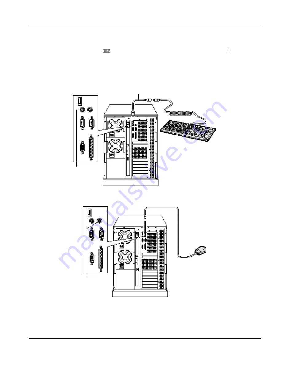
Connecting a Keyboard or Mouse

Although the interface connector for the keyboard and that for the mouse are of the same shape, connect the 
keyboard with the connector having


mark, and connect the mouse with the connector having


mark. 

Connect the keyboard with the system equipment via the extension cable (attached to the system equipment). 
Fix ferrite core (attached to the system equipment) onto the portions of the keyboard and the mouse that connect to 
the system equipment.

Connecting a Keyboard

Connecting a Mouse

Keyboard

Extension cable (attached to system equipment)

Keyboard 
interface 
connector

Mouse interface 
connector

Mouse

Summary of Contents for VisionBase 8450H

Page 1: ...Hitachi PC VisionBase 8450H R Server Product Guide ...

Page 2: ...t you keep separate permanent written records of all important data and perform periodic backups Data may be lost or altered in virtually any electronic memory product under certain circumstances Therefore Hitachi PC assumes no responsibility for data loss or data otherwise rendered unusable whether as a result of improper use repairs defects or any other causes Hitachi PC assumes no responsibilit...

Page 3: ...wer On 28 Turning Power Off 29 Connecting External Devices 30 Connecting Displays 30 Connecting a Keyboard or Mouse 31 Connecting a Printer 32 Connecting a Power Cord 32 Connecting an Uninterruptible Power Supply Unit Optional 33 Connecting an External Disk Array Unit Optional 35 3 Installing Optional Devices 37 Installing Locations for Option Devices 37 Expansion Slots 37 Extended Storage Bays 38...

Page 4: ...100 What You Can Set with Device Selections 103 Other Functions 106 List of Setting Values for SCSI Devices 108 Error Messages for the SCSI Utility 110 Returning the Settings to Defaults 112 Returning the Settings of the Setup Information to Defaults 112 Returning the SSU Settings to Defaults 112 Returning the SCSI Utility Settings to Defaults 113 List of Utility Settings 113 ...

Page 5: ...r connectivity to other rack option devices Feature Description Operator Panel Provided with Power switches and Status lights for system operation Extended Storage Bays Bays 7 to 9 Bays 1 to 6 One 3 5 inch diskette drive bay accessible from front Three extended storage Bays for SCSI devices Six Extended Storage Bays for internal hard disks located to the left of the 3 5 inch drive 3 5 inch Floppy ...

Page 6: ...on 2 Hitachi PC VisionBase 8450H R Server Chassis Front View 1 Operator Panel 2 Extended storage bays 7 9 3 3 5 inch floppy disk drive 4 Front door 5 Front door lock 6 Storage bay door 7 Extended storage bays 1 6 8 Caster 1 2 3 4 5 6 7 8 1 2 3 6 7 5 VB 8450H VB 8450R ...

Page 7: ...sion switch NOT TO BE USED Do NOT press this switch This feature is not supported 4 RESET switch 5 POWER switch 6 POWER lamp 7 ACCESS lamp 8 ERROR lamp 9 HDD ERROR lamp 10 FAN ERROR lamp 11 PS ERROR lamp 12 Headphone jack 13 Headphone volume control 14 CD Busy indicator 15 Manual eject hole 16 CD Open close button 2 1 5 4 3 6 7 8 9 10 11 12 13 14 15 16 1 2 3 4 5 VB 8450H VB 8450R 6 7 8 9 10 11 ...

Page 8: ...al interface connector COM2 5 Serial interface connector COM1 6 Display interface connector 7 Parallel interface connector 8 Expansion slot PCI 1 to 7 9 Expansion slot ISA 1 shared with PCI slot 7 10 Power Connectors 11 Power status lamp 12 Power supply 1 and 2 standard 13 Power supply 3 optional 14 Error interface connector 15 PTL connector 1 2 3 4 5 6 7 9 8 10 11 13 12 1 2 3 4 5 6 7 8 9 15 14 13...

Page 9: ...ty changes rapidly Location near a device such as motor generating electric noise Location near a device generating strong magnetic field Location with much dust and litter Location with much vibration Location where corrosive gas is generated such as sulfur dioxide hydrogen sulfide chlorine gas or ammonia Location without ventilation such as within a fully enclosed shelf or box Item Allowable ran...

Page 10: ...the system equipment properly If you lose it it will become necessary to replace the entire key unit If such is the case consult the store where you bought the equipment While the system is being started up avoid executing keyboard resetting Ctrl Alt Delete otherwise a system error will occur Keyboard and Mouse Prevent water from splashing on the keyboard or mouse When cleaning use soft cloth such...

Page 11: ...0 Store cartridges containing data in a temperature range of 5 to 32 C If the cartridge to be used has been placed somewhere that exceeds the allowable temperature range leave it at ordinary room temperature at least two hours before use Use of a cartridge with its service life exhausted could cause a drive failure or data destruction While not in use remove the cartridge from the equipment If you...

Page 12: ...e on both types of drives use the internal DLT for formatting the cartridge before use the recording density is 20GB 40GB uncompressed compressed Extended Board Check that the slot connectors are engaged properly then insert an extended board Forcible insertion with the slot connectors not engaged could cause pins to be bent or broken Other Option Devices Use extreme care to protect expansion devi...

Page 13: ... system equipment See Operator Panel on page 11 2 Extended storage bays 7 to 9 Used to install various types of SCSI devices including removable devices such as internal CD ROMs and internal SCSI devices See Chapter 3 Installing Optional Devices on page 37 3 3 5 inch floppy disk drive Provided as standard in every type of system The following types of floppy disks are usable 2DD 720kB format 2HD 1...

Page 14: ...ended storage bays 1 to 6 Used to install internal hard disks See Chapter 3 Installing Optional Devices on page 37 8 Caster lock NOTE To unlock the caster reach under the system equipment and lift up the lever Pressing down the lever in the center of the caster in front of the system equipment will lock the caster to fix the system equipment To press down the lever open the front door then reach t...

Page 15: ...all point pen or a similar thing when you press the RESET switch 5 Expansion switch this feature is not supported Not to be used Do not press this switch 6 POWER lamp Comes on when you press the POWER switch to turn on the system equipment 7 ACCESS lamp Comes on while an internal hard disk is being accessed 8 ERROR lamp Comes on when an error occurs in a hard disk a fan or power supply 9 HDD ERROR...

Page 16: ...that uses a serial interface such as a modem 6 Display interface connector Used to connect a display 7 Parallel interface connector Used to connect a device that uses a parallel interface such as a printer 8 Expansion slots PCI 1 to 7 Used to connect PCI specification boards up to 7 Slot numbers are 1 2 3 etc from the top 1 9 Expansion slot ISA 1 Used to install an ISA specification board 1 10 Pow...

Page 17: ...se the open close button to remove the CD ROM 3 Headphone jack Used to connect the stereo pin plug for the headphone 4 Headphone volume Used to adjust the volume level of the headphone 5 Busy indicator Comes on while an internal CD ROM is being started Blinks during access 6 Manual eject hole Manual eject hole Used to forcibly extract the CD ROM when it cannot be extracted in an ordinary way becau...

Page 18: ... removal of a cartridge you cannot use the eject button to remove the cartridge 3 Busy indicator Indicates the operation status according to the way of lighting Normal status Erroneous status Tape lamp Clean lamp Operation status Data is being loaded or unloaded or self test is in progress when power is turned on Data is being read or written Loading completed online Tape lamp Clean lamp Operation...

Page 19: ...ected by the select button from the cartridge magazine to the drive this is referred to as loading 5 Magazine present lamp 6 Operator alert lamp 7 Tape activity lamp The three lamps indicate operation status as in the following table Lamp Lighting Operation status Magazine present Comes on in green A cartridge magazine has been inserted Blinks in green A cartridge magazine is being inserted checke...

Page 20: ...e number of lines the larger the tape capacity NOTE The details of the LED messages are listed in the table below No Message Type Operator alert lamp Meaning 1 At BOD Error On A space command detected an unexpected BOD The current tape position is BOD 2 At EOD Error On A read or space command detected an unexpected EOD The current tape position is BOD 3 Bad Media Error Blinking The tape in use is ...

Page 21: ...r On Hardware error Contact the store where you bought the system equipment or call the maintenance personnel 19 FW Check Status The firmware upgrade data is being checked for compatibility 20 FW Data Err Error Blinking The firmware upgrade data is incorrect Use the correct upgrade data 21 FW Program Status The drive is being upgraded with new firmware 22 FW Upgrade Status The firmware upgrade dat...

Page 22: ...pply was abnormal 39 Partition Status The drive is switching a two partition tape to a different partition 40 Partition 1 too large Error On Formatting failed because the size for one partition is too large Decrease the partition size or use a longer tape 41 Read Status The drive is reading data from tape 42 Read Fail Error Blinking Reading data failed Reset the position of the data and retry 43 R...

Page 23: ...e current tape position is immediately after the erroneous data area Reset the data position and retry 57 Tape Stuck Error Blinking A cartridge is stacked in the drive Attempt to forcibly eject the cartridge If the error still recurs contact the store where you bought the system or call the maintenance personnel 58 Unloading Status The drive is unloading a cartridge The drive is ejecting a cartrid...

Page 24: ...s button to change the recording density the recording density for writing data is fixed at 20 0 format the maximum recording density for uncompressed data is 20GB Use ARCserve to specify whether compressed or uncompressed write is to be used See the manual for ARCserve for details of specification methods The initial status is compressed write the Compress lamp is on 4 Handle operation lamp 5 Cle...

Page 25: ...tion lamp Comes on in orange The cartridge is write protected Goes off You can write data to the cartridge Lamp Lighting Operation status 2 61 1 This function is not supported Comes on in yellow Data is recorded in the cartridge with the 2 6 format up to 2 6GB Blinks in yellow The 2 6 format has been selected 2 2 Data is recorded in the cartridge with another recording density 6 01 Comes on in yel...

Page 26: ... Ejecting a Cartridge Inserting a cartridge into the drive 1 Check that the handle operation lamp is on and lift the handle 2 Insert the cartridge until it is stopped and fixed 3 Press down the handle NOTE When a cartridge is inserted and made operable a particular operation sound is emitted ...

Page 27: ...g a cartridge from the drive 1 Press the Unload button While the tape is rewound the tape in use lamp blinks 2 When the handle operation lamp comes on lift the handle 3 Remove the cartridge 4 Press down the handle After lifting the handle wait for a while before removing the cartridge ...

Page 28: ...s button to change the recording density the recording density for writing data is fixed in 35 0 format the maximum recording density for uncompressed data is 35GB Use ARCserve to specify whether compressed or uncompressed write is to be used See the manual for ARCserve for details of specification methods The initial status is compressed write the Compress lamp is on 4 Handle operation lamp 5 Cle...

Page 29: ...ou can write data to the cartridge Lamp Lighting Operation status 2 61 1 This function is not supported Comes on in yellow Data is recorded in the cartridge with the 2 6 format up to 2 6GB Blinks in yellow The 2 6 format has been selected 2 2 Data is recorded in the cartridge with another recording density 6 01 Comes on in yellow Data is recorded in the cartridge with the 6 0 format up to 6 0GB Bl...

Page 30: ... Ejecting a Cartridge Inserting a cartridge into the drive 1 Check that the handle operation lamp is on and lift the handle 2 Insert the cartridge until it is stopped and fixed 3 Press down the handle NOTE When a cartridge is inserted and made operable a particular operation sound is emitted ...

Page 31: ...g a cartridge from the drive 1 Press the Unload button While the tape is rewound the tape in use lamp blinks 2 When the handle operation lamp comes on lift the handle 3 Remove the cartridge 4 Press down the handle After lifting the handle wait for a while before removing the cartridge ...

Page 32: ...after processing stops for 10 minutes or more at the time of booting the OS press the POWER switch to turn off and then turn on the power The POWER switch stores power on off information When a power outage occurs when you use a UPS you can start the system equipment immediately after power is restored Wait at least 5 seconds between power on and power off operations When operating on the power su...

Page 33: ...ower off check that all devices connected have been stopped If you use an OS requiring shutdown operation be sure to perform shutdown operation before turning the power off Some peripheral devices must be turned on after the system equipment Refer to the manual attached to each peripheral device for details If power does not turned off for a while after you pressed the POWER switch cache protectio...

Page 34: ...is section explains how to connect displays to the system equipment 1 Connect the display interface cable with the display interface connector on the back of the system equipment 2 Plug in the power cord of the display Use a ground type two pole socket with a ground terminal If you use a two pole power cord with a grounding wire attach the grounding wire to the ground terminal then put in the powe...

Page 35: ...mark and connect the mouse with the connector having mark Connect the keyboard with the system equipment via the extension cable attached to the system equipment Fix ferrite core attached to the system equipment onto the portions of the keyboard and the mouse that connect to the system equipment Connecting a Keyboard Connecting a Mouse Keyboard Extension cable attached to system equipment Keyboard...

Page 36: ...r then remove the cover off the system equipment When installation is finished reattach the cover NOTE If you install an optional third power supply as a redundant power supply connect one more power cord Be sure to plug in all power cords to the same power supply system Be sure to connect to a socket with a grounding terminal Power cord attached to printer Printer Parallel interface connector Pri...

Page 37: ... a tripping of the circuit breaker The Hitachi PC VisionBase 8450H R Server allows the use of an external UPS Use a UPS suited for your OS Refer to the manual attached to the UPS for hardware settings Connecting to a Serial Interface NOTE You need also to make settings required to use the serial interface in the Setup Menu You can also connect to a serial interface connector COM2 Serial interface ...

Page 38: ...ng to a Mouse Interface Optional NOTE You need also to make settings required to use the serial interface in the Setup Menu If you connect a UPS to the mouse interface the mouse is unusable Mouse interface cable attached to external UPS External UPS Mouse interface connector Power cord ...

Page 39: ...bre Channel board installed in the system equipment is connected with an external disk array unit using a Fibre Channel cable Use as a Shared Disk for a Cluster System The Fibre Channel board is connected with an external disk array unit via FC AL HUB using a Fibre Channel cable A converter is connected between the FC AL HUB and the Fibre Channel cable Power cord attached to external array unit Ex...

Page 40: ...Ch 2 Installation and Use of Devices 36 Hitachi PC VisionBase 8450H R Server ...

Page 41: ...on slot ISA 1 are shared Slot name Qty Use Processor slot 4 Pentium II Xeon processor is installed Memory slot 16 The memory platter board contains 16 slots Memory DIMMs are installed in units of 4 pieces Expansion slot PCI 7 Extended boards of PCI specifications are installed Expansion slot ISA 1 Extended boards of ISA specifications are installed Power slot 3 Power units are installed Power slot...

Page 42: ...installed N N N Y N N N Fibre Channel board2 3 2 Installable when an external disk array unit DF350 is connected 3 Up to two pieces can be installed when a dual controller for an external disk array unit is supported N Y Y N N N N LAN board4 4 Up to six boards can be installed Y Y Y N Y Y Y Multi communication box1 N Y Y N N N N ISDN board1 5 5 Usable in a Windows NT environment N Y Y N N N N SVP ...

Page 43: ...eed to remove the upper and side covers and panel cover in the following steps Part name Usable extended storage bay 1 2 3 4 5 6 7 8 9 Internal hard disk 9GB 1 1 Installable as a data disk a reserve disk or a replacement disk for a disk array Y Y Y Y Y Y Internal hard disk 18GB 1 Y Y Y Y Y Y Internal CD ROM standard Y Y N Internal DAT optional N Y Y Internal DAT changer2 optional 2 Occupies two ex...

Page 44: ...lling Optional Devices 40 Hitachi PC VisionBase 8450H R Server Opening the Front Door 1 Insert the door key for front door into the front door then turn it 90 degrees clockwise 2 Pull and open the front door 2 1 ...

Page 45: ...or removing a panel cover open the storage bay door 1 Insert the dedicated door key into the storage bay door and turn it clockwise 2 Open the storage bay door by pulling it to the front Too much force on the storage bay door will deform it When opening or closing the storage bay door be sure to do it gently If you open or close the door too strongly internal hard disks might malfunction because o...

Page 46: ...alling a processor a memory DIMM or an extended board remove the left side cover NOTE The right and left side covers should be removed basically in the same way This section explains only the left side cover 1 Remove two mounting screws from the back of the system equipment 2 Holding the center of the left side cover pull the cover to the rear several centimeters then extract it to the outside 2 1...

Page 47: ...over Before removing the panel cover you need to remove the front door 1 Open the front door 90 degrees or more then extract it by lifting it a little 2 Remove six mounting screws from the front of the system equipment 3 Extract the panel cover by pulling it to the front NOTE While removing the panel cover keep the storage bay door open Guide hole Protrusion Hinge Front door 1 2 ...

Page 48: ...lanation of how to close the front door and storage bay door is omitted here Installing the Panel Cover 1 Fix the panel cover with six mounting screws 2 By aligning each protrusion of the hinge on the front door with the corresponding guide hole on the system equipment fix the front door onto the system equipment Guide hole Protrusion Hinge Front door ...

Page 49: ...e coming out that cable might be disconnected NOTE The right and left side covers should be installed basically in the same way This section explains only the left side cover 1 Fit the claws on the upper and lower portions of the left side cover into the guide holes on the system equipment then push in the cover while holding the center of the cover 2 Fix the cover with two mounting screws 1 2 Cla...

Page 50: ...cient power enabling you to keep on operating NOTE When you install an option power unit you need to add one outlet three in total 1 Remove the cover of power slot 3 on the back of the system equipment by removing four mounting screws on the cover NOTE Store the removed covers properly 2 Insert the power unit by aligning it with the guide holes then fix it with four mounting screws NOTE Make sure ...

Page 51: ...power unit Both the power lamp green and the current lamp green are on The power unit is normal One or both of the power lamp green and the current lamp green are off Check whether the power unit is installed properly If both lamps still do not come on contact the shop where you bought the power unit or call the maintenance personnel 6 Turn off the POWER switch 7 Unplug the power cord Be sure to p...

Page 52: ... divided into the following four steps Before changing the configuration of the system equipment such as internal SCSI devices or extended boards be sure to unplug the power cord and wait at least 30 seconds In some rare cases the setup data might be changed In such cases turn off the system equipment turn it on then change the settings on the Setup Menu Install a SCSI board in the system equipmen...

Page 53: ...installed In Hitachi PC VisionBase 8450H R Server you need not mount a terminating resistor onto removable devices the SCSI cable to be connected already has one mounted SCSI IDs SCSI IDs are numbers used to identify SCSI devices 0 to 6 are used Make sure that 0 is used for the SCSI ID for your starter hard disk Be sure to set SCSI IDs so that there is no duplication within the group of SCSI devic...

Page 54: ...re are two types of dualizing data mirroring and duplexing Mirroring The same data is stored in two hard disks connected to the same SCSI board Storing data requires more time than non dualized structure because data is written successively onto the two hard disks Duplexing Each of the two SCSI boards is connected to its hard disk into which the same data is written and stored at the same time res...

Page 55: ...lost Types of Disk Arrays Disk arrays are classified into six types 0 to 5 according to the RAID level Of the six types only RAID0 RAID1 RAID3 and RAID5 are currently usable The method and features of each RAID level are shown below NOTE Hitachi PC VisionBase 8450H R Server supports RAID0 RAID1 and RAID5 as well as RAID7 which is used to install hard disks used discretely in the disk array control...

Page 56: ...ard disks required 2 fixed Advantage 100 data redundancy is ensured Even if one of the two hard disks fails it will be switched to the other hard disk to continue read write operation Disadvantages The hard disk capacity required doubles because a mirrored disk with the same capacity is required A read write operation during data rebuilding will result in lower performance ...

Page 57: ...arge data because data is striped in bytes If a hard disk within the array fails the lost data is computed based on the array parities enabling the read write operation to continue By replacing the hard disk you can rebuild the data without interrupting your current task Disadvantages This type of disk array is unsuitable for transaction processing unsuitable for PC server OS processing because da...

Page 58: ...transaction processing because data is striped in block If a hard disk within the array fails the lost data is computed based on the array parities enabling the read write operation to continue By replacing the hard disk you can rebuild the data without interrupting your current task Because array parities are distributed to each hard disk you can have the advantages of parallel processing through...

Page 59: ...ed mode During a degraded mode operation an additional hard disk failure will disable the disk array to rebuild data resulting in loss of all data Be sure to replace the failed disk immediately and rebuild data NOTE The RAID0 disk array cannot rebuild data because it does not dualize data nor create parities Hot plug When the disk array operates in degraded mode you need to replace the failed disk...

Page 60: ...450H R Server Flow of failure recovery operation This section explains the flow of failure recovery for the RAID5 disk array that operates with five disks using two examples one with a reserve disk and the other with no reserve disk When a reserve disk is used ...

Page 61: ...he number of disk arrays to be used and the RAID level then the number of hard disks to be used and whether or not to use a reserve disk Hitachi PC VisionBase 8450H R Server contains six extended storage bays to which you can install a hard disk You can build a disk array as shown in the following example One disk array configuration ...

Page 62: ...n 2 Install internal hard disks disk array controller boards and internal SCSI cables onto the system equipment See Installing a SCSI Device on page 62 for details of installation 3 Make settings for disk arrays using the disk array maintenance utility See the attached Disk Array maintenance Utility Handbook for details of settings ...

Page 63: ...he same However if a reserve disk exists you need to be aware of some notes on operation See Reserve Disk on page 60 for details Installing Location for Hard Disks It is recommended that you mount hard disks for the same disk array in successive extended storage bays for the purpose of system administration You are also recommended to record configuration of disk arrays If reserve disks are mounte...

Page 64: ... spare for either disk array Hot spare for hard disks will change the disk array configuration as follows A failure occurs in hard disk A 1 in disk array A A failure occurs in hard disk B 1 in disk array B A failure occurs in hard disk A in disk array A As a result of hot spare the reserve disk is in the same position as for the original configuration but data disks A 1 and B 1 in the disk array a...

Page 65: ... RAID level 1 or 5 on page 60 the capacity of the reserve disk is larger than hard disk A x used in disk array A therefore the hard disk after the rebuilding will contain unused unusable and useless areas The capacity of the reserve disk is the same as that of A x The reserve disk serves as a hot spare in disk array A but not in disk array B Because the capacity of the reserve disk is less than th...

Page 66: ...stalled onto extended storage bays of the system equipment Usable extended storage bays depend on the SCSI device to be installed Referring to Extended Storage Bays on page 38 check the installing positions Boards and internal SCSI devices are interconnected in the following way Expansion slot 4 Disk array controller board Internal SCSI cable Internal SCSI cable standard 50 pin narrow cable for re...

Page 67: ...oot disk array must be installed starting in extended storage bay 1 See the attached Disk Array Maintenance Utility Handbook for details The SCSI ID for an internal hard disk is automatically set according to the extended storage bay onto which it is installed as shown in the following table NOTE You need not set a terminating resistor for internal hard disks a terminating resistor is mounted on t...

Page 68: ...e bay onto which you want to install the internal hard disk When taking out the canister pull the lever to the front unlock and then extract the canister The hard disk canister has a label corresponding to the extended storage bay The following table shows the correspondence between extended storage bays and labels Extended storage bay Label 1 A1 2 A2 3 A3 4 A4 5 A5 6 A6 Lever Hard disk canister L...

Page 69: ...k on the hard disk canister with mounting screws attached to the internal hard disk 4 Insert the hard disk canister into the extended storage bay by aligning the canister with the guide When you cannot insert the canister any more lift the lever for locking Internal hard disk Hard disk canister Lever ...

Page 70: ...E See the attached Disk Array Maintenance Utility Handbook for disk array settings Example of configuration table 9GB hard disk x 2 extended storage bays 1 and 2 18GB hard disk x 4 extended storage bays 3 to 6 6 Close the storage bay door The next step is connecting cables See Connecting Cables on page 78 Installing Internal CD ROM Standard This section explains how to install an internal CD ROM o...

Page 71: ... settings on the short bar The short bar is factory set at 3 Remove short bars between pins 11 and 12 and between pins 13 and 14 You need not set a terminating resistor in internal CD ROMs because a terminating resistor has already been installed in the internal SCSI cable for removable devices Be sure to set SCSI IDs so that there is no duplication within the group of SCSI devices connected with ...

Page 72: ...ng screws from the front of the system equipment then extract the device bracket 4 Remove two mounting screws from the extended storage bay to be used then remove the bay cover NOTE Store the removed bay cover properly 5 Fix the internal CD ROM onto the device bracket with four mounting screws attached to each internal CD ROM FDD cable FDD power cable Device bracket Bay cover ...

Page 73: ...uipment The next step is connecting cables See Connecting Cables on page 78 Installing Internal DAT Optional This section explains how to install an internal DAT onto an extended storage bay Extended storage bays 8 and 9 are usable Use extreme care to protect internal hard disks from shock hitting or falling on hard material Being precision devices internal hard disks are very susceptible to shock...

Page 74: ...between the SCSI IDs and the settings on the short bar The short bar is factory set at 3 NOTE You can use internal DATs without setting a terminating resistor because a terminating resistor has already been installed in the internal SCSI cable for removable devices Store the removed short bars properly Be sure to set SCSI IDs so that there is no duplication within the group of SCSI devices connect...

Page 75: ...rom the front of the system equipment then extract the device bracket 4 Remove two mounting screws from the extended storage bay to be used then remove the bay cover NOTE Store the removed bay cover properly 5 Fix device fittings onto the internal DAT with four mounting screws attached to each internal DAT FDD cable FDD power cable Device bracket Bay cover Fix device fitting Internal DAT ...

Page 76: ...nt The next step is connecting cables See Connecting Cables on page 78 Installing an Internal DAT Changer Optional This section explains how to install an internal DAT changer onto extended storage bays The height of the internal DAT changer is approximately twice the height of one extended storage bay so use extended storage bays 8 and 9 Use extreme care to protect internal hard disks from shock ...

Page 77: ...tween the SCSI IDs and the settings on the short bar The short bar is factory set at 3 NOTE You can use the internal DAT changer without setting a terminating resistor because a terminating resistor has already been installed in the internal SCSI cable for removable devices Store the removed short bars properly Be sure to set SCSI IDs so that there is no duplication within the group of SCSI device...

Page 78: ...crews from the front of the system equipment then extract the device bracket 4 Remove two mounting screws from the extended storage bay to be used then remove the bay cover NOTE Store the removed bay cover properly 5 Fix the internal DAT changer onto the device bracket with four mounting screws attached to the internal DAT changer FDD cable FDD power cable Bay cover Device bracket ...

Page 79: ...Optional This section explains how to install an internal DLT onto extended storage bays The height of the internal DLT is approximately twice the height of one extended storage bay so use extended storage bays 8 and 9 NOTE This section explains internal DLT The same applies to internal DLT In internal DLT a wide 68 pin type is used Use extreme care to protect internal hard disks from shock hittin...

Page 80: ...n the SCSI IDs and the settings on the short bar The short bar is factory set at 3 NOTE You can use the internal DAT changer without setting a terminating resistor because a terminating resistor has already been installed in the internal SCSI cable for removable devices Store the removed short bars properly Be sure to set SCSI IDs so that there is no duplication within the group of SCSI devices co...

Page 81: ...ndard 3 Remove two mounting screws from the front of the system equipment then extract the device bracket 4 Remove two mounting screws from the extended storage bay to be used then remove the bay cover 5 Fix the internal DLT onto the device bracket with four mounting screws attached to the internal DLT FDD cable FDD power cable Bay cover Device bracket ...

Page 82: ...is connecting cables See Connecting Cables on page 78 Connecting Cables Connect power cables and internal SCSI cables with SCSI devices See Installing Locations for SCSI Devices on page 62 for how internal SCSI cables should be interconnected Use extreme care to protect internal hard disks from shock hitting or falling on hard material Being precision devices internal hard disks are very susceptib...

Page 83: ...es for removable device and power cables with SCSI devices on extended storage bays 7 to 9 Also connect an FDD cable and FDD power cable with the floppy disk drive NOTE An internal SCSI cable for removable device has already been connected to the master board Use the power cables provided in the lower portion of the system equipment Unclamp and remove the cables from there then connect them to the...

Page 84: ...hi PC VisionBase 8450H R Server 3 If you install an internal DLT use the internal SCSI cable to connect the master board with the internal DLT This completes the installation of SCSI devices Internal SCSI cable optional Connector Master board ...

Page 85: ... module VRM attached to each processor starting in VRM slot 1 You need to install a terminator for processor in processor slots with no processor installed Before changing the configuration of the system equipment such as internal SCSI devices or extended boards be sure to unplug the power cord and wait at least 30 seconds In some rare cases the setup data might be changed If so turn off the syste...

Page 86: ...nstalled in processor slot 1 Install processors in processor slots 3 and 4 in the same way Install terminators for processor in the same way as for processors 1 Disengage the claw of the cover for processor slot 2 then open the processor slot 2 Remove the terminator for processor from processor slot 2 Opening the two levers at the same time will release the terminator from the connector Then hold ...

Page 87: ... slot until it stops then close the levers simultaneously NOTE When you install a terminator for processor you also need to install levers See Installing a Lever onto the Terminator for Processor on page 85 for details 4 Close the cover NOTE If the claw of the cover cannot be inserted properly the processor is probably inserted halfway Check whether the levers are closed properly ...

Page 88: ...e processor in VRM slot 2 Push in the VRM until the claws of the VRM slot are engaged Removing Processors Remove processors in the reverse procedure to their installation however remove a VRM in the following way Removing a VRM Raise the claws on both ends of the VRM slot then remove the VRM Claw 1 2 Claw ...

Page 89: ...ed to the system equipment onto the terminator in advance Paying attention to the direction of the lever and the installing locations and stretching out the lever insert it into the guide hole NOTE When installing make sure that the terminator for processor shown on the right comes in an upper position Use sufficient care to prevent lever installing locations from bending Terminator for processor ...

Page 90: ...ation are as follows Memory platter board Order of installing memories Memory DIMMs should be installed starting from the least memory slot number Number of memories installed Memory slots 1 4 5 8 9 12 13 16 1 4 x 1 l 2 4 x 2 l l 3 4 x 3 l l l 4 4 x 4 l l l l Memory platter board Memory slot 1 Memory slot 2 Memory slot 5 Memory slot 6 Memory slot 9 Memory slot 10 Memory slot 13 Memory slot 14 Memo...

Page 91: ...l it stops 2 Remove the two mounting screws from the memory bracket then pull and extract the memory bracket Memory Slot Memory Capacity 1 4 5 8 9 12 13 16 512MB standard Install 1 0GB Install Install 1 5GB Install Install Install 2 0GB Install Install Install Install Memory DIMMs contains some parts that are susceptible to static electricity Before handling memory DIMMs let static electricity be ...

Page 92: ...ase 8450H R Server 3 Holding both ends of the memory platter board extract the board straight horizontally 4 Keeping open the locks on the right and left of the memory slot insert the memory DIMM Proper installation of the memory DIMM will close the locks ...

Page 93: ...ard with the guide insert the board straight horizontally 6 After inserting the claw of the memory bracket into the guide hole on the system equipment fix it with mounting screws 7 Pull the master bracket to the back then fix it with two mounting screws 7 7 6 Memory bracket Guide hole Master board bracket ...

Page 94: ...ns Installing PCI Boards Extended boards conforming to the PCI specification are as follows Disk array controller board standard Fibre Channel board optional LAN board optional Multi communication box optional ISDN board optional SVP board optional Extended boards contains some parts that are susceptible to static electricity Before handling extended boards let static electricity be released from ...

Page 95: ...the memory bracket then extract the bracket by pulling it to the front 3 Remove two mounting screws then remove the slot bracket and slot cover NOTE Store the removed slot covers properly 4 Aligning the connector side with the slot and the left end of the board with the slot guide and holding both ends of the board push in the board NOTE You need not align a short size board with the slot guide Me...

Page 96: ...R Server 5 Fix the slot bracket with two mounting screws Mounting screws must be installed in expansion slot PCI 1 and expansion slot ISA 1 SVP board Optional Connect the IMB interface cable attached to the SVP board with the board in advance 4 5 IMB interface cable ...

Page 97: ...g the IMB interface cable remove the memory platter board 6 Insert the claw of the memory bracket into the guide holes on the system equipment then fix it with mounting screws 7 Pull the master board bracket to the back then fix it with two mounting screws Removing extended boards Remove extended boards in the reverse procedure to their installation IMB interface cable IMB connector Power unit 7 7...

Page 98: ...ISA boards 1 Remove two mounting screws from the brace at the back of the system equipment then pull the master board bracket to the front until it stops 2 Remove the mounting screws from the memory bracket then extract the bracket by pulling it to the front 3 Remove the mounting screws then the slot cover NOTE Store the removed slot covers properly Memory bracket Master board bracket 1 1 2 Slot b...

Page 99: ...guide 5 Fix the slot bracket with two mounting screws Mounting screws must be installed in expansion slot PCI 1 and expansion slot ISA 1 6 Insert the claw of the memory bracket into the guide holes on the system equipment then fix it with mounting screws 7 Pull the master board bracket to the back then fix it with two mounting screws Removing ISA boards Remove ISA boards in the reverse procedure t...

Page 100: ...Ch 3 Installing Optional Devices 96 Hitachi PC VisionBase 8450H R Server ...

Page 101: ...using the SCSI Configuration Utility SCSI Utility below Flow of Operation with the SCSI Utility The flow of operation with the SCSI Utility is as follows The SCSI Utility must be installed after an SCSI device is installed A driver must be installed after the SCSI utility is executed See Procedure of Installing a Driver attached to the system for the driver installing procedure ...

Page 102: ...S such as Windows NT requires a special operation such as shutdown Check the manual of your OS Checking the SCSI ID You can check the SCSI ID either with the SCSI Utility or from the SCSI BIOS display at the time of system startup When the system is started Press Ctrl C to start Symbios Configuration Utility is displayed on the screen followed by the display below The ID column shows the SCSI IDs ...

Page 103: ...d for the SCSI device s connected Name Adapter name Port Num Port number IRQ Current Currently usable or not Next Boot Usable or not when the system is started next time NvRAM Found NvRAM is provided or not 2 Menu items Choose these menus as required See Other Functions on page 106 for details of each item 3 Cursor You can move the cursor shadowed portion with arrow keys SYM53C810 is displayed for...

Page 104: ...ontroller 1 In the Main Menu of the SCSI Utility choose the SCSI controller The following submenu is displayed 2 Choose Adapter Setup The following Adapter Setup screen is displayed To change the setting of an item move the cursor to that item then press key From the list of items displayed select the one you want with arrow keys then press key See descriptions in SCAM Support on page 101 onward f...

Page 105: ...rotocol In ordinary circumstances use the default Off On Effective Off Ineffective default Parity Used to specify whether or not to make a parity check for the SCSI bus effective In ordinary circumstances use the default On On Effective default Off Ineffective Host SCSI ID Used to set an SCSI ID for the SCSI controller In ordinary circumstances use the default 7 0 15 7 is the default Scan Order us...

Page 106: ...mstances use the default 2 1 to 10 2 is the default Help An explanation in English of the Adapter Setup screen is displayed Pressing the space key or any other key will clear the explanation Restore Default Setup Returns the setting for each item in the Adapter Setup screen to defaults Exit This Menu Terminates the operation on the Adapter Setup screen then returns to the original menu If you chan...

Page 107: ...E The figure below is an example for the Narrow SCSI controller SYM53C810 If you selected the Wide SCSI controller SYM53C896 the display contents will differ slightly First SCSI devices with SCSI IDs 0 to 7 are displayed In this example only the SCSI device with SCSI ID 0 is connected Each of the lines with DevX N A indicates that no SCSI device is connected for the SCSI ID corresponding to X NOTE...

Page 108: ...layed 5 Press key or choose Exit this menu The menu for step is displayed 6 Press key or choose Exit this menu The following menu is displayed Unless you changed settings in step 3 you will return to the Main Menu 7 Choose Save Changes This saves the settings and returns to the Main Menu If you want to return to the Main Menu without saving the settings choose Cancel Changes To not return to the M...

Page 109: ... Read Write I O Timeout secs Used to set time out length for read write operation If you choose this item a numeric entry field is displayed Enter a value you desire in this field then press the Enter key In ordinary situations use the default 10 Scan for Device at Boot Time Used to specify whether or not to scan this device at the time of startup No No to scan Yes To scan default Scan for SCSI LU...

Page 110: ...ou can Set with Adapter Setup on page 100 and What You Can Set with Device Selections on page 103 Change Adapter Status Used to specify whether or not to activate deactivate SCSI devices collectively for each SCSI controller that they are connected to Choosing this item will display the following screen Move the cursor to the SCSI controller for which you want to change the setting then press key ...

Page 111: ...alled You can choose this item only when the number of SCSI controllers is 5 or more NOTE Hitachi PC VisionBase 8450H R Server does not allow installation of option SCSI boards Display Mode Used to specify whether or not to display information about SCSI devices by SCSI BIOS on the screen at the time of system startup Verbose Displays information Default Terse Does not display information Mono Col...

Page 112: ...er Quit Terminates the SCSI Utility If you changed settings within the SCSI utility the following message is displayed Press the space key or any other key to restart the system equipment List of Setting Values for SCSI Devices The settings for SCSI devices are shown below ...

Page 113: ...Ch 4 System Environment Settings Hitachi PC VisionBase 8450H R Server 109 The settings for SCSI devices are shown below Continued ...

Page 114: ...to narrow Explanation An error occurred at wide negotiation so processing is performed with the SCSI bus width switched to 8 bit mode It is possible that the target side firmware is faulty Message VelifyElTorito XXXXXXXX Failed Explanation An error occurred while booting CD ROM according to the El Torito specifications The media might be damaged Message Device has an unsupported sector size Explan...

Page 115: ...led Explanation The PCI system BIOS has not assigned any I O address to the board The system has a problem in a portion other than this board Message Failed to add deviceÅCtoo many devices Explanation Too many SCSI devices are to be connected Up to 24 SCSI devices can be connected Message Calculated number of heads is too large Explanation The header size of the drive s boot partition block is inc...

Page 116: ...e SSU automatically set to a value other than the default to avoid the conflict To return PCI board settings to defaults 1 Turn off the system equipment 2 Remove all PCI boards from the slots 3 Start the SSU 4 After saving the settings on Resource Configuration Add in in the SSU terminate the SSU then turn off the system equipment 5 Reinsert the PCI boards into the slots 6 Turn on the system equip...

Page 117: ... each item see the relevant chapter Setup Menu After returning the setting to defaults you need to set each item once again Item Hitachi PC VisionBase 8450H R Server Setting Values Main Menu System Time To be set by the user System Date To be set by the user Legacy Diskette A 1 44 1 25MB 3 Legacy Diskette B Disabled Hard Disk Pre Delay Disabled Primary Master None ÅAPrimary Slave None Type Auto Mu...

Page 118: ...Option ROM Scan Enabled Enable Master Enabled Latency Timer 0080h I O Device Configuration Serial port A Enabled Base I O address 3F8 Interrupt IRQ 4 Serial port B Enabled Base I O address 2F8 Interrupt IRQ 3 Parallel port Enabled Mode ECP Base I O address 378 Interrupt IRQ 7 DMA channel DMA1 Floppy disk controller Enabled PS 2 Mouse Enabled Use Multiprocessor Specification 1 4 Large Disk Access M...

Page 119: ...Clear Set User Password Enter Set Administrative Password Enter Password on boot Disabled Fixed disk boot sector Normal Secure Mode Timer 2 hr Secure Mode Hot Key Space Secure Mode Boot Disabled Video Blanking Disabled Floppy Write Protect Disabled Server Menu System Management unsupported System Event Logging Enabled Clear Event Log No Assert NMI on AERR Enabled Assert NMI on BERR Enabled Assert ...

Page 120: ... Console Redirection unsupported Com Port Address Disabled IRQ None Baud Rate 19 2K Flow Control CTS RTS CD Processor Retest No EMP Password Switch Disabled EMP ESC Sequence XXXX EMP Hungup Line String XXXXXXXX Modem Init String XXXXXXXXXXXXXXXX High Modem Init Modem Space EMP Access Mode Disabled EMP Restricted Mode Access Disabled EMP Direct Connect Modem Mode Direct Connect Boot Menu Floppy che...

Page 121: ...rd Removable Devices 1 Legacy Floppy Drives Maximum Number of I20 Drivers 1 Message Timeout Multiplier 1 Exit Menu Exit Saving Changes Exit Discarding Changes Load Setup Defaults Load Custom Defaults Save Custom Defaults Discard Changes Save Changes Item Hitachi PC VisionBase 8450H R Server Setting Values ...

Page 122: ...board Floppy Controller Enable Primary On board IDE Controller Disable Primary Channel On board Communication Devices Group Serial Port 1 Configuration 3F8h IRQ 4 Serial Port 2 Configuration 2F8h IRQ 3 Parallel Port Configuration 378h IRQ 7 Parallel Port Mode Extended Capabilities Parallel Port DMA1 Floppy Drives Group Floppy Drive A Options 3 5 inch 1 44 1 25MB drive Floppy Drive B Options Disabl...

Page 123: ...led Item Hitachi PC VisionBase 8450H R Server Setting Values Boot Device Priority Removable Devices Hard Drive ATAPI CD ROM Drive Hard Drives Bootable Add in Cards Item Hitachi PC VisionBase 8450H R Server Setting Values Admin Password User Password Options Hot Key Disabled Lock Out Timer 2Hours Secure Boot Mode Disabled Video Blanking Disabled Floppy Write Protect Disabled Reset Power Switch Lock...

Page 124: ...up Delay Secs 2 Deivce Selections Removable devices ID 0 6 Sync Rate MBytes sec 10 or 201 Width bits 8 or 16 2 Disconnect On Read Write I O Timeout secs 10 Scan for Device at Boot time Yes Scan for SCSI LUNS Yes Queue Tags On Initial Boot Device No Format Device Verify Host Adapter ID 7 Sync Rate MBytes sec 10 or 802 Width bits 8 or 163 Disconnect On Read Write I O Timeout secs 10 Scan for Device ...

Page 125: ...bose Mono Color Color Language 1 10 is set for the Narrow SCSI controller 20 for the Wide SCSI controller 2 10 is set for the Narrow SCSI controller 80 for the Wide SCSI controller 3 8 is set for the Narrow SCSI controller 16 for the Wide SCSI controller 4 Off is set for the Narrow SCSI controller On for the Wide SCSI controller Item Hitachi PC VisionBase 8450H R Server Setting Values ...

Page 126: ...Ch 4 System Environment Settings 122 Hitachi PC VisionBase 8450H R Server ...

Reviews: