4-2
Chapter 4
Safety function
4.4.2
How to input STO signal
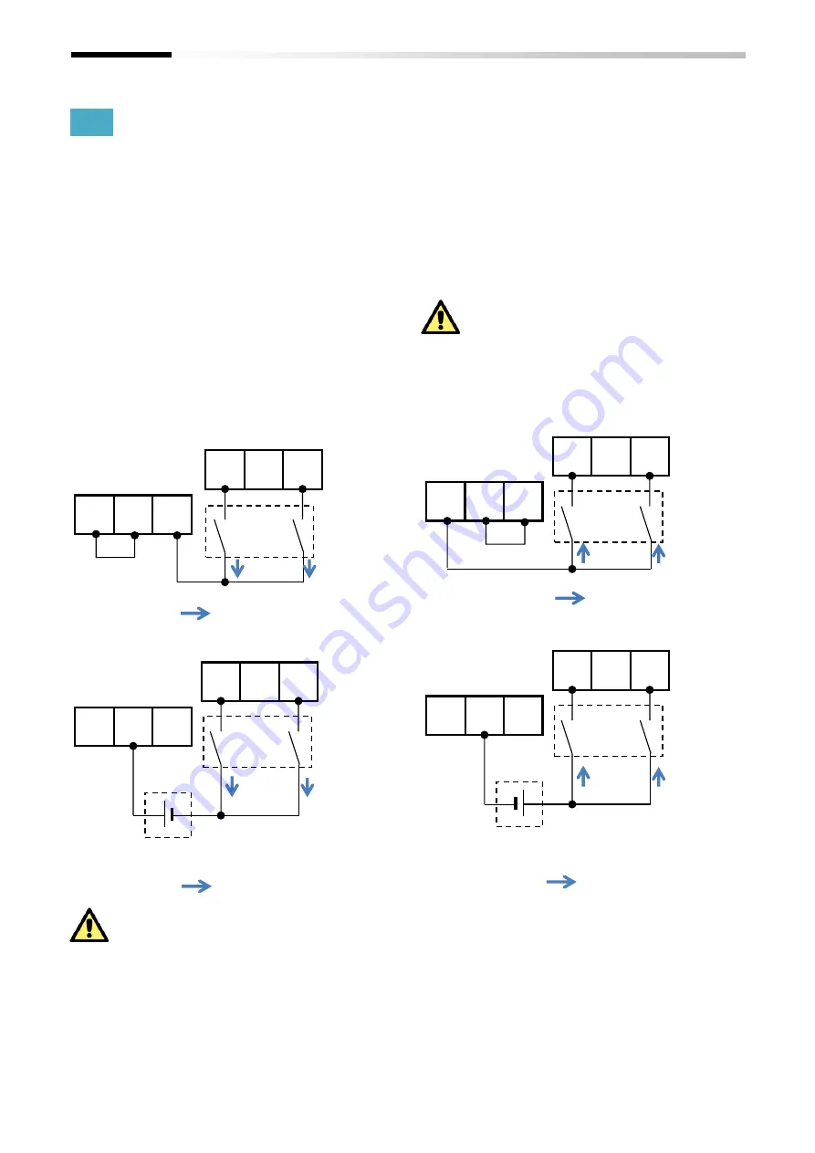
The voltage source for STO signal input is selectable from
the internal DC24V power supply (P24S terminal) or an
externally prepared DC24V power supply.
When using an external DC24V power supply, please
remove the jumper-wire (between P24S-STC or CMS-STC)
on the STO input terminal.
The external DC24V power supply must be SELV
(EN/IE60950) or PELV (EN/IEC60204).
■
Wiring Example
■
Internal power supply with “Sink” logic
■
External power supply with “Sink” logic
See Chapter 11 for the specification of the STO terminal
In case of using the internal 24V power supply, the input
logic “Sink” or “Source” of the STO inputs can be configured
by changing the connecting position of the jumper-wire.
(See the wiring examples below)
By turning off the external switches (contacts) connected
to the STO inputs (see the figures of the wiring examples
below), the STO function is activated and the output to the
motor is shut off.
Refer to the User’s Guide of SJ-P1 for the detailed
information for wiring on I/O terminal.
■
Internal power supply with “Source” logic
■
External power supply with “Source” logic
P24S
STC
CMS
ST1
ST2
STC
:
Direction of current flow
Jumper- wire
Switches
External DC24V power supply (SELV or PELV)
P24S
STC
CMS
ST1
ST2
STC
:
Direction of current flow
Switches
Jumper-wire
removed
P24S
STC
CMS
ST1
ST2
STC
:
Direction of current flow
Jumper-wire
Switches
P24S
STC
CMS
ST1
ST2
STC
Switches
Jumper-wire
removed
External DC24V power supply (SELV or PELV)
:
Direction of current flow


