background image

• In order to prevent an internal temperature increase, maintain a space of 10cm (4 inches

: For a desktop set-up) or more between the sides and other objects such as walls, etc.,
so that the ventilation holes are not blocked.(*)

CAUTION

12

INSTALLATION INSTRUCTIONS

Installation

Use one of the special mount units to install this product.  A mount of insufficient strength or inadequate design can cause overturning or
dropping and result in fire, electrical shock or injury.  Please note that our company assumes absolutely no responsibility for personal injuries
or property damage caused by use of other mount units or improper installation. 

WARNING

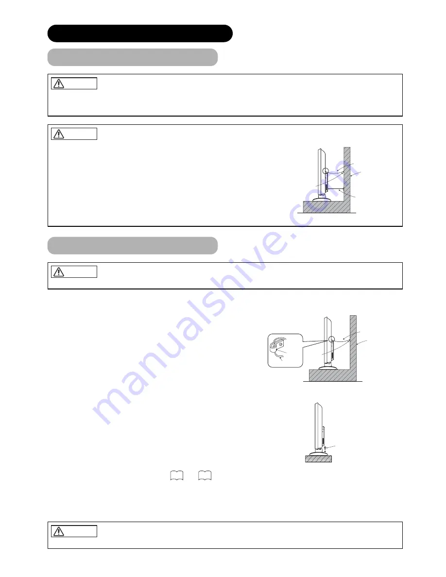
Have this unit mounted in a stable place. Take measures to prevent it from tumbling down to avoid possible physical injury.

CAUTION

Loosen a cord or chain enough whilst operating power swivel to avoid possible physical injury.

CAUTION

10cm or more

*

Cord or chain

Clamp

Wall or Pillar

Anti-tumble measures

Securing to a wall or pillar

Using a commercially available cord, chain and clamp, secure the set to a firm wall or pillar.

Securing desktop

1) Using wood screws (two), fasten the set to the clamping screw holes on the rear of the

stand as shown.

2) Using commercially available wood screws, secure the set firmly in position.

Read SAFETY INSTRUCTIONS (        to        ) carefully to ensure maximum safety before pro-
ceeding to these steps:

• Choose an appropriate site and install the product on a level table where the stand is secure.

• Install the monitor to have ready access to a power socket available.

• Make sure that the power switch of this device is turned off.

Hook

Cord or chain

Clamp

Cord or chain

Wall or Pillar

Two places

Wood screw

4

7

Summary of Contents for PW2 42PD7500

Page 1: ...500 USER S MANUAL READ THE INSTRUCTIONS INSIDE CAREFULLY KEEP THIS USER S MANUAL FOR FUTURE REFERENCE For future reference record the serial number of your monitor SERIAL NO The serial number is located on the rear of the monitor 42PD7500A ...

Page 2: ...re Notes on lnstallation Work This product is marketed assuming that it is installed by qualified personnel with enough skill and competence Always have an installation specialist or your dealer install and set up the product HITACHI cannot assume liabilities for damage caused by mistake in installation or mounting misuse modification or a natural disaster Note for Dealers After installation be su...

Page 3: ...ased the product FEATURES Large screen high definition plasma display panel The 42 inch colour plasma display panel with a resolution of 1024 H x 1024 V pixels creates a high definition large screen aspect ratio 16 9 and low profile flat display Free from electromagnetic interferences from geomagnetic sources and ambient power lines the panel produces high quality display images free from colour m...

Page 4: ... notice Whilst meticulous care has been taken in the preparation of this manual you are requested to notify your dealer or us should you have any comments views or questions about our product Fully understand the prerequisites to using the product such as hardware and software specifications and constraints in using the product We are not held liable for damages caused by improper handling of the ...

Page 5: ...or foreign objects could result in fire or electrical shock Use special caution in households where children are present If liquids or foreign objects should enter the monitor immediately turn off the power switch disconnect the power plug from the power outlet and contact your dealer Do not place the monitor in a bathroom Do not expose the monitor to rain or moisture Do not place flower vases pot...

Page 6: ...diately for emergency treatment Do not allow the battery to be exposed to fire or water Avoid fire or high temperature environment Do not hold the battery with metallic tweezers Keep the battery in a dark cool and dry place Do not short circuit the battery Do not recharge disassemble or solder the battery Do not physically impact the battery Use only the battery specified in the manual of this mon...

Page 7: ...ace near fire A wet place such as bathroom or shower room Place where you can trip over it Always vibrating or strongly vibrating places Distorted or unstable places How to view the monitor If you use the monitor in too dark a room your eyes may become tired Please use it in a reasonably bright room Avoid direct rays of the sun to the screen in order to prevent eye fatigue Your eyes will get fatig...

Page 8: ...trong rays Any strong rays such as direct sun rays or room lighting onto the remote control sensors could invalidate the remote control Avoid radio interference Any interfering radiation could cause distorted images or noises Avoid radio generator such as a mobile telephone transceiver etc around the monitor Set the sound volume at a suitable level It is better to keep the volume level low and clo...

Page 9: ...ing images of identical patterns such as static images for long periods of time can be reduced by displaying a completely white screen for about 1 2 hours after terminating the display Using Luminance Manager function works to reduce image retention when displaying images on the four corners such as TV station logos and clock display Settings can be made using Screen Wipe and Luminance Manager fro...

Page 10: ...ceiver 10 Indicating lamp The main power switch is located at the back on the lower surface Main power switch 20 20 Caution when moving the main unit As this product is heavy whenever it is moved two people are required to transport it safely Whenever the unit is moved it should be lifted forwards using the two handgrips at the back and the unit should then be held at the base on both sides for st...

Page 11: ...emote control sensor and within 30 degrees on both sides Within 30 degrees About 5m About 3m Within 30 degrees About 3m Do not use new and old batteries together The batteries could explode or leak resulting in fires physical injury or stains When loading batteries observe their correct polarities as marked on the product If loaded in the wrong direction the batteries could explode or leak resulti...

Page 12: ...Press this button to display input signal TIME Pressing this button can indicate the time by On Screen display when receiving a TV programme on the screen including TELETEXT service with the time information 2 1 DVD and SAT PROGRAMME SELECT Press these buttons to select a TV programme directly FREEZE MULTI MODE Press this button to change the picture to freeze mode Press it again to return to norm...

Page 13: ... avoid possible physical injury CAUTION Loosen a cord or chain enough whilst operating power swivel to avoid possible physical injury CAUTION 10cm or more Cord or chain Clamp Wall or Pillar Anti tumble measures Securing to a wall or pillar Using a commercially available cord chain and clamp secure the set to a firm wall or pillar Securing desktop 1 Using wood screws two fasten the set to the clamp...

Page 14: ...rminal it is possible to view the same image as on the main unit But it is possible to monitor only the composite video signal from AV1 AV4 input that is displayed on the screen at the time Whilst watching TV or DTT broadcasting it is possible to switch between TV and DTT from AV1 At the time SCART OUTPUT in Setup menu need to be set to TV or DTT Refer to Secure connecting cables to the stand with...

Page 15: ...noise to appear on the screen Avoid using indoor antenna as this may be affected by interference Please use CATV net or outdoor antenna Keep the power cord as far away from the antenna wire as possible If there are noise appearance in the picture of VHF Low band channel please use the double shielded cable not provided for RF LEADS to reduce the noise Connecting to an Audio Visual Device continued...

Page 16: ...computer being connected the use of an optional conversion adapter or the adapter provided with the personal computer may be necessary in some cases For details refer to the instruction manual of the personal computer or ask the personal computer manufacturer or your local retail dealer 58 62 D sub DVI Monitor rear panel Speaker R Speaker L Power cable connector Power cord To signal output termina...

Page 17: ... direction is opposite on the Right and Left speaker systems 3 Attach the speaker connecting cables to the monitor Make sure the ferrite core is toward the monitor side Right Side Rear of the monitor Clamps Right Side Rear of the monitor Twist off the screws Speaker holder Monitor Speaker System Speaker holder Screws x 4 Screws x 4 Aluminum trims Screwdriver NOTE In the event of the speakers not a...

Page 18: ...rminals Hold down the lever Release the lever Insert the wire How to connect the speaker cables Speaker side Make sure to secure the power cable and the connecting cables for other audio visual devices except the speaker connecting cables to the clamps of the monitor stand and the rear of the monitor When the monitor is swivelled the connectors may drop out and generate heat It could cause fire an...

Page 19: ...e figure and pull them down until it sounds click Fasten the side input with the speaker holder by the screw Refer to about the connection of side input See the below figure how to treat the cable 2 Mount the side input into the securing holder Fasten the side input with the speaker holder by the screw See the below figure how to treat the cable Without the speaker unit 1 Attach the holder for the...

Page 20: ... other connections Connect the power cord to this device Connect the power cord plug to the power outlet Power Cord Connection Use only the power cord provided Do not use a power supply voltage other than that indicated AC220 240V 50Hz as this may cause fire or electric shock CAUTION ...

Page 21: ...rol or the SUB POWER button on the control panel is ON Lights orange Off Power Save When the main power switch is ON and the POWER button on the remote control or the SUB POWER button on the control panel is ON This indicates that it is in Power Save mode When the indicating lamp lights in orange or the message No Sync Signal Power Save or Invalid Scan Freq appears on the screen there is something...

Page 22: ...ing TV mode Auto is the mode using WSS Wide Screen Signals which identify the picture format movies and programmes are broadcast in Various broadcast stations now transmit WSS It can be detected and the monitor automatically switch to the correct format However some broadcasters do not transmit WSS so this monitor will not recognize which format is being transmitted Therefore Default Zoom setting ...

Page 23: ... to view images which were created in 4 3 mode This mode allows 4 3 content to be viewed without picture distortion During RGB Input RGB1 set to DVI PC and RGB2 set to RGB Real mode gives the image of the same shape as it is displayed on a computer monitor This mode is only available for VGA 640 X 480 and WVGA 864 X 480 The size for WXGA 1366 X 768 will be fixed as Full mode Display area selection...

Page 24: ...be lowered by pressing the button whilst the audio is mute The muting can be cancelled by pressing the button or MUTE button whilst the audio is mute The audio from the headphone terminal is not mute The audio from the speaker is automatically mute whilst connecting the headphone to the headphone terminal of the side input AV4 When the MUTE button of the remote control is pressed again the audio w...

Page 25: ...ld cause the failure of the stand Do not put hands or faces close to the monitor whilst operating the swivel function It could cause a physical injury Use special caution in households where children are present Do not put any object like a vase near the monitor in swiveling area It would cause a breakage of the object and or a failure of the stand Place the monitor on the stable location or the s...

Page 26: ...ls and go out in approximately 60 seconds Refer to about the information banner 1 ABCDE Min BG OFF TV Off timer On timer TV position Name Sound mode AV1 Composite Min OFF VIDEO Off timer On timer Input mode Signal mode RGB2 RGB H 48 4kHz V 60 1 Hz Min OFF RGB Off timer On timer Input mode Signal mode Input horizontal frequency Input vertical frequency RECALL button 32 Now Next 1 ABCDE Signal Level...

Page 27: ...t the 2 pictures mode will display 4 pictures Press and button to select picture A or picture B indicated by a red triangle For the pictures on the right side press and button to select picture The input display on the selected picture would change green The TV DTT channel can be changed by pressing the CHANNEL UP DOWN button on the remote control The audio can be output only from picture A in 4 p...

Page 28: ...in Sub Sub 1 Sub 2 Sub 3 Main NOTE Even if the input of the horizontal vertical synchronizing signal or video signal stops in the multi picture display the mode will not change to power save mode Please be careful since image retention will occur if display is left in a multi picture display state for a long period of time NOTE About 720p 50Hz 720p 50Hz can support for AV3 AV5 and RGB 1 DVI STB on...

Page 29: ... and the other still The Strobe mode will display 12 pictures with the last picture active whilst other 11 windows are still Pressing the FREEZE button again changes the screen back to the normal picture This function is also available from video input mode besides TV mode Refer to the table for Freeze function as below A A 5 1 2 3 4 5 6 7 8 9 10 11 12 Active Split Strobe Split Strobe TV 쑗 쑗 DTT 쑗...

Page 30: ...ton to display the Channel List Menu screen Use the and button to select the channel to be adjusted and then use the and button to select function Press RED GREEN buttons to display the next or previous page If there is no operation for a period of one minute the Menu screen will be closed automatically 30 37 Main Menu Channel List Installation Configuration Timers Language TV Setup Common Interfa...

Page 31: ...Reset to the factory setting 1 Press MENU button on the remote control 2 Select Installation on the main menu 3 Select First Time Installation 4 The message appears as shown Press Yes Searching for New Channels 1 Press MENU button on the remote control 2 Select Installation on the main menu 3 Select Add New Channels 4 Choose either Automatic Search or Manual Search Automatic Search recommended sea...

Page 32: ...losest channel Selecting from the On screen Channel List 1 Press MENU button on the remote control 2 Select Channel List 3 Use button to move through the list and RED GREEN to display next or previous page 4 Press OK to select the channel along with a quarter screen image of the selected channel 5 Press MENU button again to return the normal full screen CHANNEL LIST 1 BBC ONE 2 BBC TWO 3 ITV 1 4 C...

Page 33: ... channel with the code The password dialogue is displayed Enter the parental Lock code Refer to regarding the parental Lock code Set as a favourite channel Only selected channels will appear when using CHANNEL UP DOWN button on the remote control to change channel The icon appears to identify it as the favourite channel To activate this setting Favourite Mode needs to be turned ON from the Configu...

Page 34: ...it Press 0 for full screen TV HOME SHORTCUTS BACK BBCi MENU B B C 1 Weather B B C Weather BBC ONE DIGITAL TERRESTRIAL TELEVISION DTT OPERATION continued Utilizing the Information Tool continued No Yes Interactive services cannot be used while subtitles are on Would you like to turn subtitles off now TV TEXT button COLOUR buttons RED GREEN YELLOW BLUE SUB TITLE button Buttons on Remote Control This...

Page 35: ...e i Press UP DOWN to navigate OK to watch the highlighted channel RIGHT to toggle to the next event RED GREEN to scroll page up down More i Watch Next Event Navigate OK DIGITAL TERRESTRIAL TELEVISION DTT OPERATION continued Utilizing the Information Tool continued 7days EPG 1 Press GUIDE button to display EPG screen 2 Select Channels with button 3 Show programmes on channels in 7days by the follow...

Page 36: ...00 21 00 12 05 2003 Active 2 BBC ONE 01 00 01 00 01 01 2000 Inactive 3 BBC ONE 01 00 01 00 01 01 2000 Inactive 4 BBC ONE 01 00 01 00 01 01 2000 Inactive 5 BBC ONE 01 00 01 00 01 01 2000 Inactive More i Edit Timer Exit Toggle Mode OK MENU 19 54 11 05 2003 Programme Reminder can remind you that the desired programme is about to start whilst you are watching another channel A box appears to ask you t...

Page 37: ...rom the next box appeared select Set Lock Key 6 Enter new password twice 7 Press MENU to return to normal viewing in order to activate the lock Channel Lock With Channel Lock any channel can be locked so that it cannot be selected for viewing without four digits PIN code See above 1 Press MENU button on the remote control 2 Select Channel List 3 Highlight the channel which you want to lock with bu...

Page 38: ...that module s menu Each module display different item depending on the module inserted Common Interface Figure 1 Common Interface Menu with modules inserted into the slots Media Guard TV Setup menu can be accessed from the DTT main menu As selecting Setup it jumps to the TV main menu containing Analogue TV functions Refer to regarding the settings for details Picture Audio Timer Function Setup Sel...

Page 39: ...MENU button to display the Main Menu screen 2 Press the OK button to display the Picture Menu screen Use the and button to select other items 3 Use the and button to select the item to be adjusted and then use the and button to adjust example Contrast Press the RETURN button to return to the previous screen If there is no operation for a period of one minute the Menu screen will be closed automati...

Page 40: ...f Scart Output TV Select Set Return OK Setup Teletext Language West Europe East Europe Cyrillic Greek Turkish Select Return Exit Setup Auto Tuning Country Greece Hungary Iceland Ireland Italy Netherlands Norway Poland Search Select Set Return OK Setup Auto Tuning Country Portugal San Marino Spain Sweden Switzerland Turkey United Kingdom Search Select Set Return OK Setup Auto Tuning Country Austria...

Page 41: ...ssing and button And press OK button to complete it Press the RETURN button to exit Set the position number 1 199 and AV00 or channel number by CHANNEL UP DOWN button Auto Tuning Search Manual Tuning Position Name Sound System Colour System Skip At first select the channel entry method entering a two digit chan nel number CH entering a two digit S band number or entering a three digit frequency MH...

Page 42: ...eyed out This should correspond to the signal mode of the signal from the equipment that is connected to AV3 video input terminal Normally set this to Auto The signal mode of the input signal will be automatically recognized If the input signal contains much noise or has a low level at Auto and the operation is found erratic set this to match the input signal DTT TV Monitor Scart Output DTT AV1 Sc...

Page 43: ...is function is only for RGB2 It s not available greyed out for RGB1 DVI PC Adjust for maximum character clarity This function is only for RGB2 It s not available greyed out for RGB1 DVI PC Adjust for clear character visibility This function is only for RGB2 It s not available greyed out for RGB1 DVI PC The original factory settings for the items of this Menu page can be restored by pressing the OK...

Page 44: ... connected to RGB2 D sub terminal This step should be set only when Component is selected on the 1st step This should correspond to the signal mode of the signal from the equipment that is connected to RGB2 D sub terminal Normally set this to Auto The signal mode of the input signal will be automatically recognized If the input signal contains much noise or has a low level at Auto and the operatio...

Page 45: ...wered On It is recommended to set to Off to reduce the panel image retention This is used to reduce power consumption for video input when there is no video signal Setting it On will lead the monitor to the standby mode when the AV input with no signal is selected This selects the display condition of the FREEZE mode between Split 2 pictures and Strobe 12 pictures This selects the screen display s...

Page 46: ...n Picture Dynamic YNR Off CNR Off Film Mode On PAL Comb Filter On LTI Off CTI Off Black Enhancement Off Auto Colour Off Reset Reset Select Set Return OK Auto Colour Off Next Prev On Off Return Picture Dynamic Colour Temp Adjust Colour Management Colour Decoding Select Set Return OK Picture Colour Temp Adjust On Amplitude Red 63 Green 0 Blue 31 Cut Off Red 31 Green 0 Blue 31 Reset Reset Select On O...

Page 47: ...nhances red and weakens green Enhances green and weakens red This is not available to adjust when receiving PAL SECAM signal Then the character will be greyed out Adjust for most realistic skin colour PAL Comb Filter This is available only when receiving a PAL composite signal Turn On to reduce the discolorations in fine picture detail and provides purer colour YNR Performs picture signal noise re...

Page 48: ... adjusts R G B level or hue to make the colour appear natural for the user s preference These settings are independently stored in each of the 4 Colour Temperature modes When select Hue the display will be grey to indicate it is not available when receiving PAL SECAM Off On RGB R G B Magenta Magenta is weakened Magenta is strengthened Red Red is weakened Red is strengthened Yellow Yellow is weaken...

Page 49: ...bdued for increased overall darkness Black is set off for increased overall brightness Adjust to preference Picture Enhancement Sets the clarity of small details to the desired level Colour Temperature Normally set to Normal Colour Temp Adjustment Amplitude Cut Off Reset Turn On when you wish to change colour temperature is required to adjust depending on the user s preference The original factory...

Page 50: ...s Adjust to preference Balance Suppresses right side sound Suppresses left side sound Adjust to preference Headphone Volume Headphone Select Turns down the volume Turns up the volume off the function waiting to reset This is to set the volume for headphone The audio from the speaker is mute when connected to headphone terminal A B During the 2 pictures mode the audio will be output from headphone ...

Page 51: ...service directly rather than through a TELETEXT service subject to subtitle service broadcasting This allows the screen to return to the TV mode temporarily whilst searching for a required text page When the required text page has been received the page number will be displayed at the top left of the screen Press the CANCEL button again to display the TELETEXT screen Each of these buttons selects ...

Page 52: ...gistered Screen Saver Screen Wipe Black Side Panel Video Power Save Freeze Mode Default Zoom Panel Life Luminance Manager System Colour System AV1 AV2 AV3 AV4 Video Input AV1 AV3 Scart Output RGB1 RGB2 Auto Adjust Horizontal Position Vertical Position Horizontal Clock Clock Phase Input Level Frequency Display WVGA Type WXGA Mode Vertical Filter Frequency Mode Function Setup OTHER FUNCTIONS Automat...

Page 53: ... the CH I II button to select between stereo and mono sound Each time the button is pressed or force mono appear cyclically on the screen When receiving NICAM signals NICAM display will appear as below NICAM Sound multiplex signal received Select or force mono to hear the STEREO or MONO broadcast respectively NICAM signal received Red Green Red Green 8 왓 Monaural sound broadcast When a monaural pr...

Page 54: ...ayer and Set Top Box by pressing the following buttons on the remote control simultaneously DVD Selection Makers of DVD player Set Maker Set Type Makers of DVD player Set Maker Set Type HITACHI FUNAI Pioneer Panasonic TOSHIBA Philips JVC SAMSUNG Sony Sharp 1 3 1 2 3 4 5 6 7 8 9 RCA 0 1 Mitsubishi 1 ONKYO 3 1 ZENITH 1 THOMSON 1 SHINCO 1 SKYWORTH 1 BUBUKO 1 DENON 2 1 1 6 1 4 1 4 1 2 1 1 1 4 1 2 1 2 ...

Page 55: ...ck RGB mode Changes in the signal status are displayed on the screen as they arise Status Display Action When Mode Display is set to ON the input signal is switched or when the RECALL button is pressed A guide is displayed for the input terminal and the horizontal and vertical sync frequency When the sync signal is no longer detected A guide displays No Sync Signal and Power Save for approx 5 sec ...

Page 56: ...tion matches the connection terminal No Sync Signal The display image appears flowing slant wise Text displayed across the screen appears vertically streaked with the characters in vertical columns blurred Adjust the dot clock frequency and phase Adjust the dot clock frequency first the dot clock phase next RGB input Text displayed across the screen appears blurred A fine pattern flickers when dis...

Page 57: ...t of connecting device Refer to Connecting to an Audio Visual Device and Recommended Signal List Images from AV5 HDMI are not displayed 42 43 27 13 61 Coarse horizontal stripes appear in FULL display There are locations on the screen that are different from the periphery Points that do not light points with brightness different from that of the periphery points with colour different from that of t...

Page 58: ...he button and select Setup 7 Press the OK button The Setup Menu will be displayed 8 Press the button and select Horizontal Clock Display fine patterns as characters or a vertical striped pattern over the entire screen during Horizontal Clock adjustment 9 Press the or button and search for clear characters over the entire screen 10 Perform adjustment for symptom 2 below when the characters are blur...

Page 59: ...rminals Input terminals Input terminals RF Video System Input signals Input signals Sync signals Recommended signal Recommended signal RF input Video input Output Signal Temperature Relative humidity Net dimensions excluding Speakers Stand Net weight excluding Speakers Stand Resolution Display dimensions Operating 5 C to 35 C Storage 0 C to 40 C Operating 20 to 80 Storage 20 to 90 non condensing A...

Page 60: ...instances when correct display is not possible In this case use H V separate sync H V composite sync S input connector pin specifications HDMI connector pin specifications DVI terminal DVI D Pin Input signal 1 R PR CR 2 G or sync on green Y 3 B PB CB 4 No connection 5 No connection 6 R GND PR CR GND 7 G GND Y GND 8 B GND PB CB GND 9 No connection 10 GND 11 No connection 12 SDA 13 H sync or H V com...

Page 61: ...quency MHz Remarks Signal Name Resolution Vertical frequency Hz Horizontal frequency kHz Dot clock frequency MHz Remarks Vertical frequency Hz No 1 2 576i 480i 576 480 50 00 59 94 15 63 15 73 3 576p 576 50 00 31 26 4 480p 480 59 94 31 47 5 1080i 50 1080 50 00 28 13 6 1080i 60 1080 60 00 33 75 7 720p 50 1 720 50 00 37 50 8 720p 60 720 60 00 45 00 Signal mode Signal Name Resolution 41 41 41 41 41 41...

Page 62: ... 쑗 EIA 861B 16 576p 720 X 576 50 00 31 25 27 00 쑗 EIA 861B 17 720p 50 1280 X 720 50 00 37 50 74 25 쑗 EIA 861B 18 720p 60 1280 X 720 60 00 45 00 74 25 쑗 EIA 861B 19 1080i 60 1920 X 1080 60 00 33 75 74 25 쑗 EIA 861B 20 1080i 50 1920 X 1080 50 00 28 13 74 25 쑗 EIA 861B No VGA Signal Name Resolution Vertical frequency Hz Horizontal frequency kHz Dot clock frequency MHz Setup Menu Condition DVI PC DVI ...

Page 63: ...02 68 68 67 50 63 98 79 98 91 15 75 00 93 75 106 25 35 00 49 72 60 24 68 68 47 986 56 137 47 776 47 712 Dot clock frequency MHz 25 18 25 18 34 24 31 50 31 50 36 00 36 00 40 00 50 00 49 50 56 25 65 00 75 00 78 75 94 50 108 00 108 00 135 00 157 50 162 00 202 50 229 50 30 24 57 28 80 00 100 00 81 00 94 760 79 50 85 50 Remarks WVGA type On WXGA Mode 1280x768 WXGA Mode 1366x768 Signal mode The type of ...

Page 64: ...r communal use This guarantee does not cover the replacement of exhausted batteries the adjustment of user controls or aerial alignment Any parts replaced under this guarantee shall become the property of HITACHI EUROPE LTD Please note that evidence of the date of purchase will be required before any service under this guarantee is carried out Use the boxes provided below to record your TV s Model...

Page 65: ... TRADEMARK ACKNOWLEDGEMENT VGA and XGA are registered trademarks of International Business Machines Corporation APPLE and Macintosh are registered trademarks of Apple Computer Inc VESA is a trademark of a nonprofit organization Video Electronics Standard Association All brand or product names are trademarks or registered trademarks of their respective holders ...

Page 66: ...47 Milano Italia ITALY Tel 39 02 487861 Tel 39 02 38073415 Servizio Clienti Fax 39 02 48786381 2 Email customerservice italy hitachi eu com HITACHI Europe AB Box 77 S 164 94 Kista SWEDEN Tel 46 0 8 562 711 00 Fax 46 0 8 562 711 13 Email csgswe hitachi eu com HITACHI EUROPE S A S Lyon Office B P 45 69671 BRON CEDEX FRANCE Tel 33 04 72 14 29 70 Fax 33 04 72 14 29 99 Email france consommateur hitachi...

Reviews: