


6
Vacuum pumping and charge refrigerant
•
Vacuum pumping
1. Remove the service port cap of the stop valve on the gas pipe side of
the outdoor unit.
2. Connect the manifold gauge and vacuum pump to the service port of
the stop valve on the gas pipe side of the outdoor unit.
3. Run the vacuum pump. (Work for more than 15 minutes.)
4. Check the vacuum with the gauge manifold valve, then close the gauge
manifold valve and stop the vacuum pump.
5. Leave it as is for one or two minutes. Make sure that the pointer of
the manifold gauge remains in the same position. Confirm that the
pressure gauge shows -0.101MPa (or -760mmHg).
6.
Remove the manifold gauge quickly from the service port of the stop
valve.
7.
After refrigerant pipes are connected and evacuated, fully open all stop
valves on both sides of gas pipe and liquid pipe.
8. Open adjusted valve to add refrigerant.
9.
Tighten the cap to the service port.
10.
Retighten the cap.
11.
Leak test foam with halogen leak detector to check the flare nut and
brazing leaks. Use foam that does not generate ammonia (NH
3
) in the
reaction.
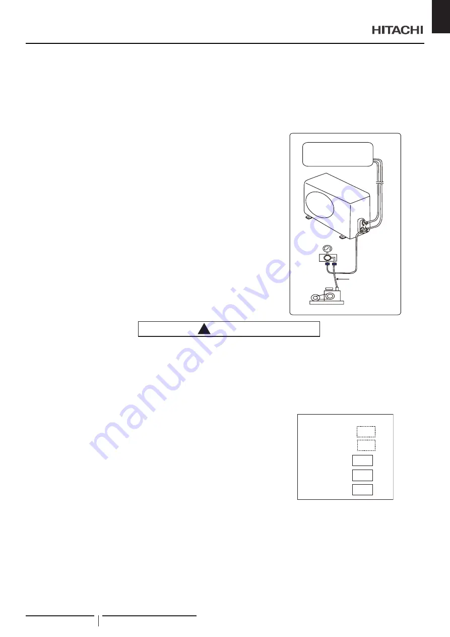
F ig.9.2
Indoor unit
Pressure gauge
Outdoor unit
Manifold
valve
Charge hose
(for R32)
Vacuum pump
!
CAUTION
An excess or a shortage of refrigerant is the main cause of trouble to the unit. Charge the correct quantity of refrigerant according
to the description in the manual.
Check refrigerant leakage in detail. If a large refrigerant leakage occurs, it will cause difficulty in breathing or harmful gases will
occur if a fire is being used in the room.
•
Additional refrigerant charge
The unit has been filled with refrigerant.
Please calculate additional charge according to “Piping Requirement”.
After finishing vacuum pump procedures, first exhaust air from charge
hose, then open valves, charge refrigerant through liquid stop valve.
At the end, please close valves and record the refrigerant charge
quantity.
This product contains fluorinated greenhouse gases covered by the
Kyoto Protocol.
Do not vent gases into the atmosphere.
Please fill in the refrigerant charge label that adhered in the proximity of
the product charging port with indelible ink.
tCO
2
:
R32
675
kg
:
kg
:
Contains fluorinated greenhouse gases.
Refrigerant
(A) GWP
Additional charge
(B) Total charge
tCO
2
=(A)x(B)/1000
INSTALLATION INSTRUCTIONS
HO2019292HA
15
EN