


--- 18 ---
Rremove dust and then
lubricate.
Replace the piston O-ring.
Correct or replace the parts.
Air leaks from Gasket (A).
O-rings are worn or
deformed.
O-rings need lubrication.
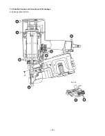
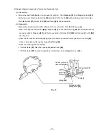
<Nail guide section>
Nail guide face is abnormal
(deformed, burrs or
damaged).
Dust sticks to the inside of
the nail guide groove, or
lubrication is needed.
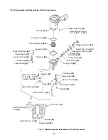
Spring is abnormal
(missing, damaged or
fatigued).
The claw ridge section of
the nail stopper is abnormal
(damaged, worn or burrs).
Tighten screws and replace
gaskets.
Replace the O-rings.
Apply grease or lubricate.
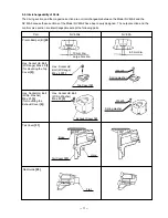
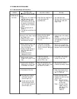
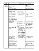
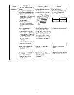
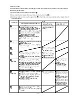
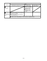
Problem
Possible cause
( : Most-common cause)
Inspection method
Remedy
1) Nails cannot
be driven.
(continued)
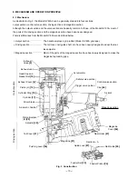
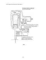
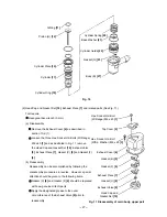
<Output section: piston,
driver blade, etc.>
Air pressure is too low.
Piston O-ring is abnormal
(worn or damaged).
Piston bumper is abnormal.
Cylinder ring is abonrmal
(removed, deformed or
damaged).
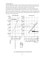
Adjust the air pressure to
5 --- 8.5 kgf/cm
2
(4.9 --- 8.3
bar, 70 --- 120 psi).
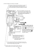
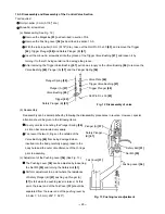
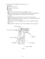
Check that the distance
between the lower end of the
nose and the lower end of
the pushing lever is
6.5 0.5 mm (0.256 0.020")
under the following
conditions.
Pull up safety plunger (B)
until it contacts plunger (A).
Pull up the pushing lever
until safety plunger (B)
contacts the safety bolts.
Check that the nail guide is
not abnormal (worn,
deformed, damaged, etc.).
Check the operation of main
nail stopper and sub nail
stopper.
Replace the abnormal parts.
Readjust the safety bolt
according to 10-3-(2).
Replace the piston bumper.
Reassemble or replace the
parts.
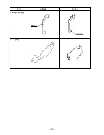
Driver blade is abnormal
(deformed, burrs or damaged).
Correct or replace the parts.
Check that a nail does not
catch on another nail in the
magazine.
Check that a nail does not
catch on some part of the
magazine.
Check the height of the nail
holder.
Collate the nails correctly
and reload the nailer with
them.
Remove burrs or deformed
part. Replace the parts.
Adjust the height of the nail
holder correctly.
<Magazine section>
<Pushing lever>
Magazine
Safety belt is not adjusted
properly.
Open the nail guide and
perform idle driving to check
that the driver blade is
returned.
Summary of Contents for NV 83A2
Page 15: ... 12 Pushing Lever 54 Part NV 83A2 NV 83A Bent Welded Cover 105 ...
Page 46: ......