--- 19 ---
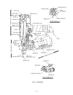
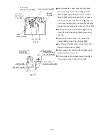
(A)
(H)
(C)
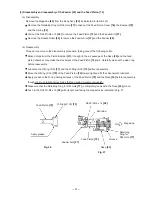
(a)
(b)
(c)
(B)
(D)
(d)
(e)
(f)
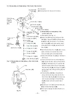
A
A
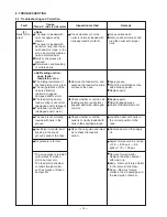
Looseness of the Hex. Socket Hd.
Bolt M5 X 20
[7]
Damage of Gasket (A)
[9]
Abnormality in the sealed faces of
the Body Ass'y
[22]
, Exhaust Cover
[8]
and the Cylinder
[20]
8-2. Possible Causes and Corrections for Air Leakage
Air leakage repairing position
Repairing step
(1) Check for abnormality in the
parts marked *(asterisk) out of
the following parts.
(2) Check for wear, scratches and
damage in the parts marked
(circle).
(3) Next, examine other portions.
(The numbers in
[Bold]
correspond to the item numbers
in Parts List and the exploded
assembly diagrams.)
Control valve section
(E)
(g)
(h)
(G)
(F)
Cross section A --- A
Air leakage portion
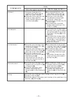
(A) Exhaust port
Cause
When the trigger is turned off
When the trigger is turned on
Abnormality in Head Valve (A)
[12]
and the Cylinder
[20]
[Wear and
deformation of the sealed face of the
(b) section]
Abnormality in the Head Valve O-ring
(I.D 16.8)
[11]
or wear, deformation
and/or breakage of Head Valve (A)
[12]
Abnormality (damage) in the Exhaust
Cover
[8]
Abnormality in Head Valve (A)
[12]
[Wear, deformation and/or breakage
of the section (a)]
* Abnormality in the inner face [the
section (a)] in the Exhaust Cover
[8]
[Deformation and dust clogging in
the section (a)]
(B) Exhaust cover
(C) Nose 1
(Feed piston passage)
Looseness of the Hex. Socket Hd.
Bolt M6 X 20
[34]
Scratched and/or broken O-ring
(1AP-3)
[32]
Abnormality in the sealed faces of
the Body Ass'y
[22]
and the Nose
[33]
(F)(G)
Summary of Contents for NV 50AF3
Page 41: ......


