background image

--- 29 ---

(b) Reassembly

Reassembly can be accomplished by following the disassembly procedures in reverse.  However, special

attention should be given to the following items.

Assemble Piston (H) [13] so that its semi-circular grooved side is facing toward the Magzine side.  (Same

as paragraph 10-2-(1)-(b))

Ensure that the air vent holes on Gasket (F) [8] are properly aligned with the matching holes in Body Ass'y [24].

(3) Head Cap [11] and related parts: (See Fig. 12.)

(a) Disassembly:

Remove Exhaust Cover [11].  (Refer to paragraph 10-2-(2).)

Remove the two Hex. Socket Hd. Bolts M5 x 25 [1] and disassemble Head Cap [11], Exhaust Valve [10]

and Gasket (G) [9].

(b) Reassembly:

Reassembly can be accomplished by following the disassembly procedures in reverse.  However, special

attention should be given to the following items.

Ensure that the air vent holes in Gasket (G) [9] are properly aligned with the matching holes in Head Cap

[11] and Exhaust Cover (B) [4].

(4) Grip Rubber

The Grip Rubber [41] assembled in the Body Ass'y [24] is not supplied singly because the disassembly and

reassembly are not easy.  When replacement of the Grip Rubber [41] is required, replace the Body Ass'y [24]

(Body Ass'y [24] comes with the Grip Rubber [41]) or install grip tape (A) according to the following procedure.

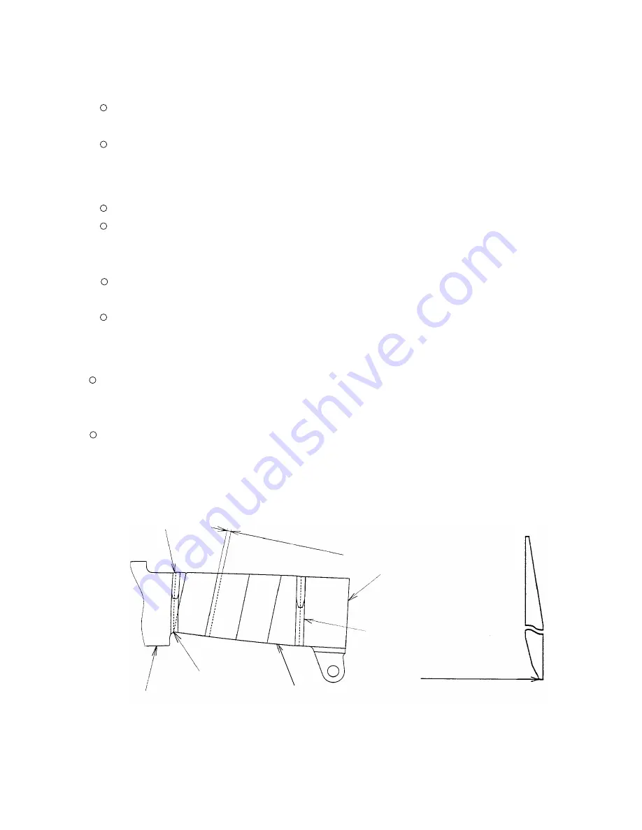
Installation of grip tape (A) and tape

Adhere the adhesive-backed grip tape (A) and the tape to the Body Ass'y [24].  First, adhere the end of grip

tape (A) under the trigger valve of the Body Ass'y [24] and wind around the Body Ass'y [24].  Wind the Tape at

both ends of grip tape (A) (see Fig. 14).  Be careful that grip tape (A) and tape cannot be removed once they

are adhered.

Fig. 14

Grip tape (A)

End of grip tape (A)

Body Ass'y [24]

Trigger valve

Winding amount: 1.5 - 3 mm

(0.06 - 0.12")

End of grip tape (A)

Tape

Tape

Summary of Contents for NV 45AB2

Page 1: ...POWER TOOLS TECHNICAL DATA AND SERVICE MANUAL COIL NAILER NV 45AB2 SPECIFICATIONS AND PARTS ARE SUBJECT TO CHANGE FOR IMPROVEMENT LIST No E004 Mar 2002 N MODEL NV 45AB2 ...

Page 2: ...L a symbol s is are used in the place of company name s and model name s of our competitor s The symbol s utilized here is are as follows Symbols Utilized Competitors Company Name Model Name BOSTITCH RN45B P SENCO SCN40R Q PORTER CABLE RN175 R MAX CN450R S ...

Page 3: ...nciple 10 8 3 Interchangeability 14 9 TROUBLESHOOTING GUIDE 16 9 1 Troubleshooting and Correction 16 9 2 Possible Causes and Corrections of Air Leakage 21 10 DISASSEMBLY AND REASSEMBLY 24 10 1 General Precautions in Disassembly and Reassembly 24 10 2 Disassembly and Reassembly of the Output Section 25 10 3 Disassembly and Reassembly of the Valve Section 30 10 4 Disassembly and Reassembly of the Dr...

Page 4: ...that of the Model NV 45AB and the 2 valve cylinder drive system that is well reputed for quick driving is adopted To meet the market demands the Model NV 45AB2 is equipped with a tool less nailing depth adjuster top loading magazine non slip rubber etc Applicable nails are the same as those of the Model NV 45AB The Model NV 45AB2 weighs only 2 5 kg same as the Model NV 45AB 3 APPLICATIONS Installa...

Page 5: ...NV 45AB requires operation of both the nail guide and the latch at the rear of the magazine 4 Carbide chip The carbide chips provided at the tip of the pushing lever are larger than the competitive products to prevent wear Size of carbide chip area ratio 5 Non slip rubber Although the Model NV 45AB is equipped with only a steel body guard at the side of the body a non slip rubber is added to the M...

Page 6: ...Packaging dimensions Length x Height x Width Packaging 335 mm x 155 mm x 320 mm 13 3 16 x 1 1 8 x 12 5 8 Hex bar wrench for M4 screw Code No 943277 Hex bar wrench for M5 screw Code No 944458 Eye protector Code No 875769 Sequential trip mechanism kit Single shot Code No 878226 Pneumatic tool lubricant 1 oz oil feeder Code No 877153 Pneumatic tool lubricant 4 oz oil feeder Code No 874042 Pneumatic t...

Page 7: ...are shown below However it is recommended to use genuine HITACHI nails to ensure satisfactory driving quality CAUTION Ensure that nails are as specified in Fig 1 Other nails will cause clogging of nails and subsequent damage to the nailer Min Wire collated nails Fig 1 Dimensions of nails Max 10 5 mm 0 413 10 5 mm 0 413 3 05 mm 0 120 3 05 mm 0 120 22 mm 7 8 45 mm 1 3 4 ...

Page 8: ...y depending on the type of wood moisture content and grain of wood Fig 2 Required nailing energy and nailer output energy Required nailing energy Nailer output energy 5 4 Optional Accessories Sequential trip mechanism kit Single shot Code No 878226 A sequential trip mechanism kit is provided as an optional accessory for the Model NV 45AB2 By using this optional accessory a nail is driven by pressi...

Page 9: ...110 mm 11 13 16 x 10 1 8 x 4 11 32 1 4 ltr cycle 0 049 ft 3 cycle 5 1 lbs 2 3 kg R Nail capacity 120 nails 120 nails 120 nails 120 nails 120 nails 120 nails Magazine type Material Top loading Plastic Top loading Plastic Top loading Plastic Bottom loading Plastic Top loading Plastic Top loading Plastic Driving depth adjustment mechanism Tool not required Tool not required None With wrench Tool not ...

Page 10: ...attached together with the Instruction Manual for details 7 1 Instruction Manual Although every effort is made in each step of design manufacture and inspection to provide protection against safety hazards the dangers inherent in the use of any pneumatic tool cannot be completely eliminated Accordingly general precautions and suggestions for use of pneumatic tools and specific precautions and sugg...

Page 11: ...926 302 Power operated hand tools ANSI SNT 101 1993 Portable Compressed Air Actuated Fastener Driving Tools Safety Requirements for 8 MECHANISM AND OPERATION PRINCIPLE 8 1 Mechanism As illustrated in Fig 3 the Model NV 45AB2 can be generally divided into four sections output section control valve section driving section and magazine section Although the output section and the valve section are bas...

Page 12: ... Blade 9 Adjuster Nose Cap Control valve section Body Trigger valve portion Magazine Nail holder Magazine Guard Shingle guide Magazine section Safety valve portion Driving section Output section Accumulator 1 Cylinder ring Guide base Air inlet Magazine cover Feeder Magazine Feed piston Nose Main nail stopper Guide lock Nail guide Cylinder 2 Return Air Chamber 6 Piston Bumper 7 Pushing lever Feeder...

Page 13: ... applied to the lower surfaces of the flanges located at the center portion of the Cylinder 2 forcing the cylinder upward The compressed air is thereby blocked from the upper end of the cylinder and no pressure is applied to the Piston 3 The Accumulator 1 is filled with compressed air The trigger and pushing lever are not operated and remain closed The exhaust vents are open and no air pressure is...

Page 14: ...oves downward the air below the piston is forced into the Return Air Chamber 6 When the piston passes the middle vent some of the air pressure passes into the return air chamber This supplies auxiliary air to ensure complete return of the piston Cylinder ring 2 When the trigger and pushing lever are operated The trigger and pushing lever are operated simultaneously Note If either the trigger or pu...

Page 15: ...ston 3 contacts the Piston Bumper 7 and prevents air leakage If the upper surface of the Piston Bumper 7 is damaged some air will leak As there is no O ring installed here a very small amount of air will leak from the slight clearance between the components If the operator s grip is loosened air will leak 3 If the trigger and pushing lever are kept pressed ...

Page 16: ...upper side of the piston lowers the air pressure within the Return Air Chamber 6 pushes the piston upward Note If the clearance were any larger the piston would not return if it were smaller driving force would be decreased When the trigger is released the trigger valve closes and the compressed air does not flow into the air passage The air pressure within the valve air passage is discharged thro...

Page 17: ...t A 29 Feeder A 70 The mounting portion of the magazine is different in shape Thickness 0 5 mm 2 slopes 2 5 mm 0 1 The hooks are different in shape Grip tape Mounting portion of the magazine is not thickened There is a difference Thickness 0 4 mm 1 slope 5 mm 0 2 Spare parts will be unified to the ones for the Model NV 45AB2 Nose 32 A protrusion is provided at the mounting portion of the adjuster ...

Page 18: ... for holding the magazine cover is provided Protrusion Top loading type The newly designed nail guide is required to close the magazine cover It can be mounted to the newly designed body only Following parts are common to the Model NV 45AB Plate Nut 104 Guide Base 105 Shingle Guide 107 Hex Socket Hd Bolt M5x10 108 Groove Bottom loading type ...

Page 19: ...broken Replace the abnormal parts Apply grease to the sliding surface Air passage is clogged with broken pieces of piston bumper etc Air pressure is too low Dust sticks to the feeder sliding portion of the nose or lubrication is needed Remove foreign matter Replace the piston bumper with new one Nails are not correctly loaded in the groove of the nose Check that nails are correctly loaded in the g...

Page 20: ...eed lubrication Problem Possible cause most common cause Inspection method Remedy 1 Nails cannot be driven Tighten screws and replace gaskets Replace the O rings Apply grease or lubricate Check that the nail guide is not abnormal worn deformed damaged etc Check the operation of main nail stopper and nail stopper Nail guide section Nail guide face is abnormal deformed burrs or damaged Dust sticks t...

Page 21: ... the cylinder plate is abnormal seized or damaged or lubrication is needed Trigger plunger plunger A B trigger valve bushing valve bushing or urethane ball C is abnormal seized or damaged Apply grease Replace the abnormal part Remove dust and then lubricate Cylinder inside surface is abnormal packed with dust or worn Check that nails can be driven at 4 9 bar 5 kgf cm2 70 psi Replace the part Perfo...

Page 22: ...surfaces of the O ring and the cylinder for abnormality Disassemble the exhaust valve section and check for abnormality or shortage of oil Check for shortage of grease on the sliding surface of the O ring Exhaust valve is abnormal or short of oil worn or scratches on seat side Safety belt is not adjusted properly Check that the distance between the lower end of the nose and the lower end of the pu...

Page 23: ...elding position failed Collating wires are deformed deformed in collation angle or collation pitch 4 Nails jam Nails UNIT mm inch Type B L1 L2 7 0 276 16 0 630 7 0 630 25 0 984 A Body Nail feeding is incomplete Open the nail guide and check the position of the feeder claw Check that the feeder claw holds a nail and the first nail is positioned in the injection port Check that the second claw holds...

Page 24: ... 21 9 2 Possible Causes and Corrections of Air Leakage Air leakage repair location Fig 8 ...

Page 25: ...Exhaust Valve 10 worn deformed or broken Exhaust vent Air leak part Cause When trigger valve safety valve are OFF When trigger valve safety valve are ON Inspection priorities In the table below possible causes of air leakage and their repair procedures are marked in accordance with the likelihood of possible failure 1 First priority items are marked with an asterisk 2 Second priority items seal po...

Page 26: ...ken When trigger valve ON safety valve OFF Feed piston I Between feed piston cover and nose J Cap H Slight amount of air is always leaked out of the Feed Piston Cover 66 structurally Loose Hex Socket Hd Bolt M5 x 16 44 Broken Gasket D 42 Defective seal surface of the Body Ass y 24 or Cap 43 Defective seal surfaces of Nose 32 and Feed Piston Cover 66 Broken Gasket E 65 Defective rear side O Ring 61...

Page 27: ... rings and prevent dirt entry Coat a small amount of grease a silicone based grease is recommended on the sliding portions of the nail feeding section Oil required Hitachi pneumatic tool lubricant 1 oz 30 cc oil feeder Code No 877153 4 oz 120 cc oil feeder Code No 874042 1 quart 1 ltr can Code No 876212 If the packings are damaged replace them and ensure that there is no air leakage after repair B...

Page 28: ...er 3 mm 0 118 a Disassembly See Figs 9 and 10 Remove the Machine Screw M5 x 22 39 and the Magazine Ass y 109 can be disassembled Fig 9 Roll Pin D3x30 47 Body Ass y 24 Gasket A 29 Cylinder O Ring C 26 Piston H 13 Piston Bumper 27 Machine Screw M5 x 22 39 Nail Guide 78 Magazine Ass y 109 Nylock Hex Socket Hd Bolt M5 x 16 34 Magazine Bushing 67 Nose Guard 33 Nose 32 Bumper Sheet 28 ...

Page 29: ...e semi circular grooved side is facing toward the Magazine side See Fig 11 When mounting the Bumper Sheet 28 to Piston H 13 open the cut of the Bumper Sheet 28 and put the driver blade in the Bumper Sheet 28 from its thin side facing the groove on the circumference of the Bumper Sheet 28 to the semi circular grooved side at the tip of Piston H 13 surely Reassemble Gasket A 29 so that its air vents...

Page 30: ...n and remove the Bumper Sheet 28 from the Piston Bumper 27 After removing the four Hex socket Hd Bolts M5 x 20 5 and Exhaust Cover B 4 Piston H 13 can be disassembled Next insert two of the Hex Socket Hd Bolts M5 x 20 5 into the provided threaded holes in the Cylinder Plate 16 Holding the two bolts lift upward while turning the Cylinder Plate 16 When the Cylinder Plate 16 has been removed the Cyli...

Page 31: ...Spring 19 Cylinder O Ring D 15 O Ring S 65 14 Piston H 13 Piston O Ring 12 Cylinder Ring 18 Cylinder 17 Cylinder Plate 16 Body Ass y 24 including the Grip Rubber 41 Cylinder Guide 21 Cylinder O Ring A 20 O Ring S 65 14 Grip Rubber 41 O Ring S 65 14 Cylinder O Ring B 22 Threaded hole for M5 bolts Hex Socket Hd Bolt M5 x 20 5 Cylinder Plate 16 Protector 6 Body Guard 7 ...

Page 32: ...e following items Ensure that the air vent holes in Gasket G 9 are properly aligned with the matching holes in Head Cap 11 and Exhaust Cover B 4 4 Grip Rubber The Grip Rubber 41 assembled in the Body Ass y 24 is not supplied singly because the disassembly and reassembly are not easy When replacement of the Grip Rubber 41 is required replace the Body Ass y 24 Body Ass y 24 comes with the Grip Rubbe...

Page 33: ... accomplished by following the disassembly procedures in reverse However special attention should be given to the following items Thoroughly remove any tar or dirt which may be stuck on the tip of the Nose 32 and the inside sliding portion of the Pushing Lever 38 Pay particular attention not to twist the Plunger Spring 48 and break or damage the O Rings After mounting the Valve Rubber Cover 60 on ...

Page 34: ... 51 Valve Rubber Cover 60 O Ring S 12 52 Body Ass y 24 Fig 15 Plunger B 59 Roll Pin D3 x 30 47 Trigger 58 Plunger O Ring 49 Trigger Plunger 57 Valve Packing 53 Plunger Spring 48 Trigger Valve Bushing 56 Valve Plate 55 Fig 16 Valve Bushing 51 Valve Rubber Cover 60 Plunger B 59 Groove Groove ...

Page 35: ...er 38 is 5 0 5 mm 0 197 0 020 when the Pushing Lever 38 is pushed up so that Safety Bolt 36 pushes up Plunger B 59 to a position where it in turn begins to push up Plunger A 50 When Plunger B 59 is pushed upward you will feel the slight resistance when it reaches the position where it begins to push up Plunger A 50 c On completion of adjustment securely tighten the Nut M5 37 Plunger A 50 Pushing L...

Page 36: ...e the Pushing Lever 38 from the main body Next pinch the lower tip of the Nail Guide Shaft 74 with pliers and pull down Fig 19 a Then the Shaft Ring 73 can be removed from the Nail Guide Shaft 74 and the Nail Guide Shaft 74 can be pulled out of the Nose 32 The entire nail guide section can be removed from the Nose 32 Do not remove the Nail Guide Shaft 74 with a flat blade screwdriver as shown in F...

Page 37: ...ssembly procedures in reverse However special attention should be given to the following items Prior to reassembly thoroughly remove tar dirt and other foreign matter from the latch groove on the Nail Guide 78 When reassembling the Main Stopper Spring 83 and Sub Stopper Spring 88 carefully ensure that they are properly inserted into the holes on the Main Nail Stopper 86 and Nail Stopper 87 On comp...

Page 38: ...ed Piston 63 The Feeder A 70 and Feeder Spring 69 can then be removed Next the Feed Piston 63 can be taken out of the Nose 32 Mount the Nail Guide Shaft 74 according to the following procedure see Fig 21 I Insert the Shaft Ring 73 between the protrusion of the Nose 32 and the Bolt 77 Turn the Adjuster 75 counterclockwise to narrow the distance between the protrusion of the Nose 32 and the Bolt 77 ...

Page 39: ... reassembly coat grease on the O Ring P 9 61 the Feed Piston O Rings 62 64 and the O Ring sliding portions of the Feed Piston 63 and Nose 32 However as excessive grease will cause improper movement of the Feed Piston 63 be very careful during grease application This is particularly important if the tool is to be used at relatively low air pressures Carefully clean the air passage of the Nose 32 An...

Page 40: ...haft Ring 72 that prevents the Pin 101 from coming off can be removed Insert a small flat blade screwdriver between the Holder Cap 91 and the Nail Holder 99 to widen the clearance Then the Holder Cap 91 can be removed Fig 23 At this time be careful not to scratch the Nail Holder 99 and the Holder Cap 91 Remove the Machine Screw M4 x 50 Then the Holder Shaft 95 Nail Holder 99 and other parts can be...

Page 41: ...39 Washer 40 Gasket D 42 Hex Socket Hd Bolt M5 x 10 108 Shingle Guide 107 Hex Socket Hd Bolt M5 x 14 106 Machine Screw M4 x 50 92 Magazine Cover 90 Hex Socket Hd Bolt M5 x 16 44 Cap 43 Sleeve 97 U Nut M5 96 Body 24 Plate Nut 104 Magazine Guard 103 Pin 101 Feed Shaft Ring 72 Guide Base 105 Nylon Nut M4 102 Magazine 100 U Nut M5 96 ...

Page 42: ... not operate only by depressing the Pushing Lever 38 3 Single guide portion Tools required Hex bar wrench 4 mm Spanner 8 mm or slender hd pliers a Disassembly See Fig 22 Remove the Nail Holder 99 from the Magazine Ass y 109 Remove the Hex Socket Hd Bolt M5 x 10 108 Then the Shingle Guide 107 can be removed from the Guide Base 105 Secure the U Nut M5 96 with a spanner 8 mm or a slender hd pliers In...

Page 43: ...xhaust Cover B Exhaust Valve Head Cap 60 min 50 Cylinder Plate Cylinder Guide Cylinder Cylinder Ring O ring x 7 Piston Bumper Pushing Lever Spring Feeder A Adjuster General Assembly Adjustment Cylinder Body Valve Tail Cover Nail Guide Guide Lock Main Nail Stopper Nail Stopper Nail Guide Cover Magazine Ass y Body Feed Piston O ring x 3 Feed Piston Cover Piston H Piston O ring ...

Page 44: ...14 23 24 25 26 27 28 29 30 31 32 33 34 35 36 37 38 39 40 41 42 43 44 45 46 47 48 49 50 51 52 47 52 53 54 55 56 57 49 58 59 60 61 62 63 64 65 66 67 68 69 70 71 72 73 74 75 76 77 78 79 80 81 82 83 84 85 86 87 88 89 90 90 91 92 93 94 95 96 97 98 99 72 100 101 102 103 104 105 106 107 108 501 502 503 504 505 506 96 72 90 103 106 72 108 109 109 ...

Page 45: ...GUIDE 1 22 877 124 CYLINDER O RING B 1 23 878 184 WARNING LABEL 1 24 883 889 BODY ASS Y 1 INCLUD 41 25 878 183 WARNING LABEL 1 FOR EUROPE 26 877 125 CYLINDER O RING C 1 27 878 179 PISTON BUMPER 1 28 877 993 BUMPER SHEET 1 29 883 881 GASKET A 1 30 949 818 HEX SOCKET HD BOLT M5X8 10 PCS 2 31 878 151 GUARD 1 32 883 880 NOSE 1 33 878 173 NOSE GUARD 2 34 878 181 NYLOCK HEX SOCKET HD BOLT M5X16 4 35 878...

Page 46: ...FT 1 72 877 826 FEEDER SHAFT RING 2 73 883 885 SHAFT RING 1 74 883 884 NAIL GUIDE SHAFT 1 75 883 882 ADJUSTER 1 76 883 883 ADJUSTER SPRING 1 77 958 805 BOLT 1 78 883 887 NAIL GUIDE 1 79 877 820 LOCK SHAFT 1 80 877 821 GUIDE LOCK 1 81 949 776 ROLL PIN D3X10 10 PCS 1 82 877 372 SPRING 1 83 876 681 MAIN STOPPER SPRING 1 84 949 766 HEX SOCKET HD BOLT M4X6 10 PCS 2 85 949 865 ROLL PIN D3X28 10 PCS 1 86...

Page 47: ...07 878 175 SHINGLE GUIDE 1 FOR USA 108 949 819 HEX SOCKET HD BOLT M5X10 10 PCS 1 FOR USA 109 883 893 MAGAZINE ASS Y 1 INCLUD 72 90 103 106 109 883 894 MAGAZINE ASS Y 1 INCLUD 72 90 108 FOR USA 501 877 153 PNEUMATIC TOOL LUBRICANT 30CC 1 FOR EUROPE 502 943 277 HEX BAR WRENCH 3MM 1 503 944 458 HEX BAR WRENCH 4MM 1 504 875 769 EYE PROTECTOR 1 505 878 188 CAUTION TAG 1 FOR USA 506 882 414 LEAFLET 1 FO...

Page 48: ......

Reviews: