background image

--- 5 ---

Driving depth

adjustment mechanism

With wrench

None

With wrench

With wrench

Single-touch

operation by hand

Single-touch

operation by hand

6. COMP

ARISONS WITH SIMILAR PRODUCTS

Maker

HIT

A

CHI

Air consumption at

7 kgf/cm

2

 (100 psi)

Operating pressure

Jam-release

W

eight

Dimensions

(L x H x W)

Model name

Staple capacity (Max.)

---

  8.5 kgf/cm

2

(70 

---

  120 psi)

3

6

5

 mm x

 2

5

4

 mm x 7

6

 mm

(1

4

-3

/8

" x 10

" x 3

")

N 5008AC

1.14 ltr

./cycle

(.040 ft

3

/cycle)

160

Single-touch

operation by hand

2.0 kgf (4.4 lbs.)

---

  8.5 kgf/cm

2

(70 

---

  120 psi)

3

6

7

 mm x

 2

4

5

 mm x 7

0

 mm

(1

4-

3/

8"

 x

 9-

5/

8"

 x

 2-

3/

4"

)

N 5008AB

1.24 ltr

./cycle

(.044 ft

3

/cycle)

163

2.5 kgf (5.5 lbs.)

5.6 -

--  8.4 kgf/cm

2

(80 

---

  120 psi)

3

5

6

 mm x

 2

4

8

 mm x 7

6

 mm

(1

4"

 x

 9-3/4"

 x

 3"

)

1.06 ltr

./cycle

(.037 ft

3

/cycle)

150

1.9 kgf (4.1 lbs.)

R

4.6 -

--  8.4 kgf/cm

2

(65 -

--  120 psi)

3

6

0

 mm x

 2

4

5

 mm x 7

0

 mm

(1

4-

3/

16"

 x

 9-5/8"

 x

 2-

3/

4"

)

1.17 ltr

./cycle

(.041 ft

3

/cycle)

150

2.2 kgf (4.9 lbs.)

Y

---

  8.5 kgf/cm

2

(70 

---

  120 psi)

3

7

0

 mm x

 2

8

5

 mm x 9

0

 mm

(1

4-

1/

8"

 x

 1

1-1/8

" x

 3-

1/

2"

)

1.63 ltr

./cycle

(.058 ft

3

/cycle)

160

2.4 kgf (5.3 lbs.)

U

5 -

-- 

7.1 

kgf/cm

2

(70 

---

  100 psi)

3

6

5

 mm x

 2

8

5

 mm x 7

6

 mm

(1

4

" x

 1

1-1/8"

 x

 3"

)

0.98 ltr

./cycle

(.035 ft

3

/cycle)

160

2.4 kgf (5.3 lbs.)

P

Single-touch

operation by hand

Single-touch

operation by hand

Single-touch

operation by hand

Single-touch

operation by hand

With tool

*Driving speed

 (staples/sec.) (Max.)

12.7

10.0

1

1.4

1

1.2

9.7

Applicable

staples

#16 gauge

wire

Length

Inside width

25 mm -

-  50 mm

(1" -

-  2")

7.85 mm (.309")

7.85 mm (.309")

Outside width

7/16"

25 mm -

-  50 mm

(1" -

-  2")

25 mm -

-  50 mm

(1" -

-  2")

25 mm -

-  50 mm

(1" -

-  2")

25 mm -

-  55 mm

(1" -

-  2-1/8")

19 mm -

-  50 mm

(3/4" -

-  2")

7.95 mm (.313")

9.8 mm (.386")

7.95 mm (.313")

9.5 mm (.374")

7/16"

7/16"

7/16"

1/2"

1/2"

The driving speeds shown above are the result of measurement using special experimental instruments.  Note that the actual dr

iving speed varies depending on the

  specifications of the compressor and the air hose and the conditions of the workpiece.  Exercise extra care for safety when p

erforming quick driving using the stapler

.

Summary of Contents for N 5008AC

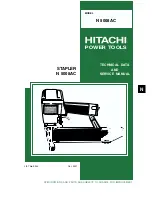
Page 1: ...POWER TOOLS TECHNICAL DATA AND SERVICE MANUAL STAPLER N 5008AC SPECIFICATIONS AND PARTS ARE SUBJECT TO CHANGE FOR IMPROVEMENT LIST No E003 Oct 2001 N MODEL N 5008AC ...

Page 2: ... symbol s is are used in the place of company name s and model name s of our competitor s The symbol s utilized here is are as follows Symbols Utilized Competitors Company Name Model Name SENCO SNS40 R PASLODE 3200 S16P Y BOSTITCH T50S4 P PORTER CABLE MS200 U ...

Page 3: ... Mechanism 8 8 2 Operation Principle 9 9 TROUBLESHOOTING GUIDE 13 9 1 Troubleshooting and Correction 13 9 2 Possible Causes and Corrections of Air Leakage 15 10 DISASSEMBLY AND REASSEMBLY 17 10 1 General Precautions in Disassembly and Reassembly 17 10 2 Disassembly and Reassembly of the Output Section 18 10 3 Disassembly and Reassembly of the Control Valve Section 21 10 4 Disassembly and Reassembl...

Page 4: ...lastic magazine The staple shoulder sliding portion of the magazine is wear resistant 2 The driving speed is faster than the Model N 5008AB thanks to the adoption of the 2 valve cylinder drive system that is well reputed in the current Models NT 65A2 NV 50AP2 and NV 45AB for easier operation detailed data is described on later pages 3 The handle is equipped with a cylindrical grip rubber for comfo...

Page 5: ... inlet Packaging dimensions Length x Height x Width Packaging 436 mm x 96 mm x 309 mm 17 5 32 x 3 25 32 x 12 5 32 Hex bar wrench for M5 screw Code No 944459 Eye protector Code No 875769 Sequential trip mechanism kit Single shot Code No 876762 Pneumatic tool lubricant 1 oz oil feeder Code No 877153 Pneumatic tool lubricant 4 oz oil feeder Code No 874042 Pneumatic tool lubricant 1 oz oil feeder Code...

Page 6: ... shown below CAUTION Ensure that staples are as specified in Fig 1 Other gauge staples and other crown width staples will cause clogging of staples and subsequent damage to the stapler Minimum Staple gauge 16 7 16 crown Fig 1 Dimensions of staple Maximum 7 85 mm 0 309 1 45 mm 0 057 1 61 mm 0 063 25 mm 1 7 85 mm 0 309 1 45 mm 0 057 1 61 mm 0 063 51 mm 2 ...

Page 7: ... vary depending on the type moisture content and grain of wood Fig 2 Required stapling energy and stapler output energy P U Y 1200 1200 Required stapling energy N 5008AC R Stapler output energy 5 4 Optional Accessories Sequential trip mechanism kit Single shot Code No 876762 A sequential trip mechanism kit is provided as an optional accessory for the Model N 5008AC By using this optional accessory...

Page 8: ... 2 kgf 4 9 lbs Y 5 8 5 kgf cm 2 70 120 psi 370 mm x 285 mm x 90 mm 14 1 8 x 11 1 8 x 3 1 2 1 63 ltr cycle 058 ft 3 cycle 160 2 4 kgf 5 3 lbs U 5 7 1 kgf cm 2 70 100 psi 365 mm x 285 mm x 76 mm 14 x 11 1 8 x 3 0 98 ltr cycle 035 ft 3 cycle 160 2 4 kgf 5 3 lbs P Single touch operation by hand Single touch operation by hand Single touch operation by hand Single touch operation by hand With tool Drivi...

Page 9: ...t attached together with the Instruction Manual for details 7 1 Instruction Manual Although every effort is made in each step of design manufacture and inspection to provide protection against safety hazards the dangers inherent in the use of any pneumatic tool cannot be completely eliminated Accordingly general precautions and suggestions for use of pneumatic tools and specific precautions and su...

Page 10: ...listed in the Instruction Manual provided with each unit While there are no specific safety regulations there are related items in various general safety regulations with which the salespersons should be familiar in order to properly advise the customer Please check your national and or local regulations for applicable items Some applicable items are outlined below The U S A OSHA 1926 102 Eye and ...

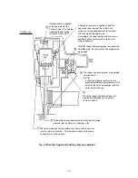
Page 11: ...for driving staples A pushing lever piece is provided to adjust the driving depth of staples with a wrench If clogged staples are caused in this section they can be easily released simply by pulling the lock lever by hand Magazine section All the parts have been newly designed for driving staples The magazine cover is opened by pulling the staple feeder backward for easy loading or replacement of ...

Page 12: ...he compressed air source air hose is connected to the nailer Air pressure is applied to the lower surface of the flanges located at the center portion of the Cylinder 6 forcing the cylinder upward The compressed air is thereby blocked from the upper end of the cylinder and no pressure is applied to the piston The Accumlator 1 fills with compressed air The trigger and pushing lever are not operated...

Page 13: ... lever are operated simultaneously NOTE If either the trigger or pushing lever is operated individually compressed air will not enter the valve air passage and the nailer will not function When the trigger and pushing lever are operated simultaneously the exhaust vents are closed Compressed air is applied to the upper side of the Exhaust Valve 2 forcing it downward and closing the Exhaust Vent 3 A...

Page 14: ... the position illustrated The lower surface of the Piston 4 contacts the Piston Bumper 9 and prevents air leakage If the upper surface of the Piston Bumper 9 is damaged some air will leak At there is no o ring installed here a very small amount of air will leak from the slight clearance between the components If the operator s grip is loosened air will leak ...

Page 15: ...ny remaining air pressure at the lower end of the piston is discharged through the clearance between the Piston Bumper 9 and the Driver Blade 7 When the air pressure at the upper side of the piston lowers the air pressure within the Return Air Chamber 8 pushes the piston upward NOTE If the clearance were larger the piston would not return if it were smaller driving force would be decreased When th...

Page 16: ...move the abnormal staples and load the magazine with normal staples Ribbon spring abnormal fatigued damaged Staple rail width too wide Magazine cover abnormal deformed damaged Adhesive fragments and wood chips are on the magazine staple feeder or staple rail Replace the defective part Replace the defective part Replace the defective part Cylinder s internal surface abnormal deposites of dirt worn ...

Page 17: ...e because the tool is not designed for such usage Adjust for 5 to 8 5 kgf cm2 4 9 8 3 bar 70 120 psi Unusable because the tool is not designed for such usage Replace the part Replace the defective part Replace the defective part Use specified staples See Magazine in item 1 Replace the part See Output section Piston driver blade etc in item 1 3 The staple is driven into the material but the head is...

Page 18: ... 15 9 2 Possible Causes and Corrections of Air Leakage Air leakage repair location A B C G D E F ...

Page 19: ...Hd Bolt M5 x 16 35 Broken Gasket D 33 Defective seal surface of the Body 20 or Cap 34 Defective Exhaust Valve 6 worn deformed or broken Exhaust vent Air leak part Cause When trigger valve safety valve are OFF When trigger valve safety valve are ON Inspection priorities In the table below possible causes of air leakage and their repair procedures are marked in accordance with the likelihood of poss...

Page 20: ...amage the O rings and prevent dirt entry Oil required Hitachi pneumatic tool lubricant 1 oz 30 cc oil feeder Code No 877153 4 oz 120 cc oil feeder Code No 874042 1 quart 1 ltr can Code No 876212 If Gasket B 4 is damaged replace it and check that no air is leaking Be especially careful to prevent the entry of foreign particles into the control valve section Use the conventional grip tape for repair...

Page 21: ...h out the Cylinder 13 from the lower part of the main body b Reassembly Reassembly can be accomplished by following the disassembly procedures in reverse However special attention should be given to the following items Ensure that the convex surface side of the Piston 9 illustrated in Fig 11 is facing toward the Blade Guide 27 side Reassembly of the Piston 9 can be most easily accomplished by inse...

Page 22: ... 19 Fig 10 Fig 11 Piston 9 Cylinder Guide 17 Piston 9 Cylinder Ring 14 Cylinder 13 Cylinder Plate 12 Body 20 ...

Page 23: ...the Exhaust Cover 3 Remove the two Hex Socket Hd Bolts M5 x 20 1 and such as illustrated in Fig 12 disassemble the Head Cap 7 the Exhaust Valve 6 and Gasket C 5 in that order b Reassembly Reassembly can be accomplished by following the disassembly procedures in reverse Ensure that the Hex Socket Hd Bolts M5 x 20 1 are properly tightened to specified torque 85 5 kgf cm 6 1 0 4 ft lb 2 Head Cap 7 Ex...

Page 24: ... the Nylock Bolt W Flange M5 x 8 54 to remove the Guard 55 Remove the Hex Socket Hd Bolt M5 x 16 35 and pull out the entire magazine section from Body 20 Remove the four Nylock Hex Socket Hd Bolt M5 x 16 26 Then Piston Bumper 22 can be removed together with the Nose 25 b Reassembly Disassembly procedures should be followed in the reverse order Note the following points Plunger B 45 is apt to come ...

Page 25: ...e Plate 48 Roll Pin D3 x 30 53 Plunger B 45 b Reassembly Reassembly can be accomplished by following the disassembly procedures in reverse However special attention should be given to the following items Be very careful in handling the Plunger Spring 40 as it can become twisted very easily To prevent the two O rings on the outside of the Valve Bushing 44 from being damaged when inserted into the b...

Page 26: ... to remove the Nose 25 Pushing Lever 31 and the magazine section Pull the Staple Feeder 63 of the magazine backward so that staples can be loaded Pull out the Pin 59 using the roll pin puller 5 mm 197 dia Pull the magazine section from the tail cover and gently put the staple feeder back as it was being careful not to lose the Shaft Ring 64 Push out the Hinge Pin 67 with a flat blade screwdriver a...

Page 27: ...erate only by actuating Trigger 52 Also check that the machine will not operate only by depressing Pushing Lever 31 Magazine Cover 57 Mount the Cover Spring 58 facing the longer arm side toward the magazine b Reassembly Disassembly procedures should be followed in the reverse order Note the following points Insert the pointed end of the Hinge Pin 67 Mount the Cover Spring 58 facing the longer arm ...

Page 28: ...EL 10 20 30 40 Fixed Variable N 5008AC Work Flow Top Cover Exhaust Cover Packing x 2 Exhaust Valve Head Cap 60 min 50 Tail Cover Blade Guide Magazine Ass y Magazine Cover Ribbon Spring Staple Feeder Pushing Lever Spring B Lock Lever General Assembly Adjustment Cylinder Body Valve Cylinder Cylinder O ring x 4 O ring x 3 Cylinder Spring Body Piston Bumper Bumper Sheet Piston Piston O ring ...

Page 29: ...AC 2001 10 30 E1 E003 501 502 503 504 1 1 2 3 4 5 6 7 8 9 10 11 12 13 14 15 10 16 17 18 10 19 20 21 22 23 24 25 26 27 28 29 30 31 32 33 34 35 36 37 38 32 39 40 41 42 43 44 45 46 47 43 48 49 50 51 52 53 54 55 56 57 58 59 60 61 62 54 63 64 65 66 67 68 69 70 ...

Page 30: ... 883 711 PISTON BUMPER 1 23 883 712 BUMPER SHEET 1 24 949 547 ROLL PIN D4X36 10 PCS 1 25 883 713 NOSE 1 26 878 181 NYLOCK HEX SOCKET HD BOLT M5X16 4 27 883 721 BLADE GUIDE 1 28 883 722 LOCK LEVER 1 29 949 685 ROLL PIN D3X20 10 PCS 1 30 877 873 SPRING B 1 31 883 714 PUSHING LEVER 1 32 877 371 NYLON NUT M5 3 33 877 131 GASKET D 1 34 880 036 CAP 1 35 949 821 HEX SOCKET HD BOLT M5X16 10 PCS 3 36 872 0...

Page 31: ...ANDLE ARM 1 57 883 718 MAGAZINE COVER 1 58 881 043 COVER SPRING 1 59 881 044 PIN 1 60 875 650 SAFETY BOLT 1 61 949 555 NUT M5 10 PCS 1 62 883 715 PUSHING LEVER PIECE 1 63 883 720 STAPLE FEEDER 1 64 881 045 SHAFT RING 1 65 881 047 RIBBON SPRING 1 66 881 039 MAGAZINE PIECE 1 67 883 719 HINGE PIN 1 68 883 717 MAGAZINE ASS Y 1 INCLUD 66 70 69 678 653 MACHINE SCREW W WASHERS M5X14 BLACK 2 70 881 040 RO...

Page 32: ...N REMARKS NO USED ITEM NO CODE NO DESCRIPTION REMARKS NO USED 10 01 N 5008AC Printed in Japan 011030N 501 944 458 HEX BAR WRENCH 4MM 1 502 875 769 EYE PROTECTOR 1 503 CAUTION TAG 1 504 882 414 LEAFLET 1 601 876 762 SEQUENTIAL TRIP MECHANISM KIT 1 602 881 768 GRIP TAPE A 1 603 880 407 TAPE 1 ...

Page 33: ......

Reviews: