6
English
ROUTER SAFETY WARNINGS
1.
Hold power tool by insulated gripping surfaces,
because the cutter may contact its own cord.
Cutting a "live" wire may make exposed metal parts of
the power tool "live" and shock the operator.
2.
Use clamps or another practical way to secure and
support the workpiece to a stable platform.
Holding the work by your hand or against the body
leaves it unstable and may lead to loss of control.
3. Single-hand operation is unstable and dangerous.
Ensure that both handles are gripped
fi
rmly during
operation.
4. The bit is very hot immediately after operation. Avoid
bare hand contact with the bit for any reason.
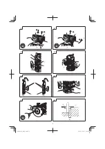
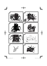
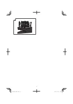
DESCRIPTION OF NUMBERED ITEMS
(Fig. 1 – Fig. 17)
1
Lock pin
&
Template
2
Wrench
*
Straight guide
3
Loosen
(
Guide plane
4
Tighten
)
Bar holder
5
Stopper pole
q
Feed screw
6
Scale
w
Guide bar
7
Depth indicator
e
Wing bolt (A)
8
Pole lock knob
r
Wing bolt (B)
9
Stopper block
t
Dial
0
Loosen the lock lever
y
Separate
!
Nut
u
Router feed
@
Threaded column
i
Workpiece
#
Cut depth setting
screw
o
Rotation of bit
$
Template guide
p
Trimmer guide
%
Screw
a
Roller
^
Bit
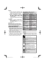
SYMBOLS
WARNING
The following show symbols used for the machine.
Be sure that you understand their meaning before
use.
M8V2: Router
Read all safety warnings and all instructions.
Always wear eye protection.
Always wear hearing protection.
Only for EU countries
Do not dispose of electric tools together with
household waste material!
In observance of European Directive 2002/96/
EC on waste electrical and electronic equipment
and its implementation in accordance with
national law, electric tools that have reached
the end of their life must be collected separately
and returned to an environmentally compatible
recycling facility.
Disconnect mains plug from electrical outlet
Class
II
tool
STANDARD ACCESSORIES
(1) Straight Guide .............................................................1
(2) Bar Holder ....................................................................1
Guide
Bar
.....................................................................2
Feed
Screw
..................................................................1
Wing
Bolt
.....................................................................1
(3) Template Guide ...........................................................1
(4) Wrench ........................................................................1
(5) Wing Bolt (A) ................................................................4
(6) Lock Spring ..................................................................2
Standard accessories are subject to change without notice.
APPLICATIONS
○
Woodworking jobs centered on grooving and
chamfering.
SPECIFICATIONS
Model
M8V2
Voltage (by areas)*
(110 V, 230 V)
Power Input*
1150 W
Collet Chuck Capacity
8 mm or 1/4"
No-load speed
11000 – 25000 min
-1
Main Body Stroke
60 mm
Weight (without cord and
standard accessories)
3.6 kg
* Be sure to check the nameplate on product as it is subject
to change by areas.
NOTE
Due to HITACHI’s continuing program of research and
development, the speci
fi
cations herein are subject to
change without prior notice.
PRIOR TO OPERATION
1. Power source
Ensure that the power source to be utilized conforms to the
power requirements speci
fi
ed on the product nameplate.
2. Power switch
Ensure that the power switch is in the OFF position. If the
plug is connected to a receptacle while the power switch
is in the ON position, the power tool will start operating
immediately, which could cause a serious accident.
0000Book̲M8V2.indb 6
0000Book̲M8V2.indb 6
2014/12/12 14:24:00
2014/12/12 14:24:00
Summary of Contents for M 8V2
Page 4: ...4 17 0000Book M8V2 indb 4 0000Book M8V2 indb 4 2014 12 12 14 23 59 2014 12 12 14 23 59 ...
Page 64: ...64 0000Book M8V2 indb 64 0000Book M8V2 indb 64 2014 12 12 14 24 07 2014 12 12 14 24 07 ...
Page 65: ...65 0000Book M8V2 indb 65 0000Book M8V2 indb 65 2014 12 12 14 24 07 2014 12 12 14 24 07 ...
Page 66: ...66 0000Book M8V2 indb 66 0000Book M8V2 indb 66 2014 12 12 14 24 08 2014 12 12 14 24 08 ...

