background image

4

RS-232C Communication

19200bps,  8N1

1. Protocol

Consist of header (7 bytes) + command data (6 bytes).

2. Header

BE + EF + 03 + 06 + 00 + C CRC_high
CRC_low : Lower byte of CRC flag for command data
CRC_high : Upper byte of CRC flag for command data

3 Command data

Command Data Chart

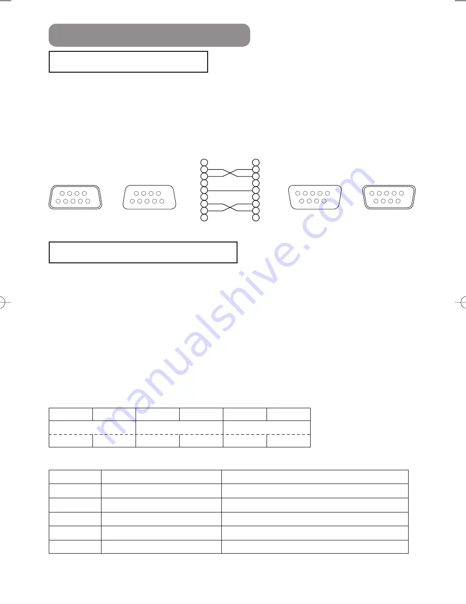
Connecting The Cable

Communications Setting

(1) Turn off the projector and the computer power supplies.
(2) Connect the CONTROL port of the projector with a RS-232C port of the computer by a RS-

232C cable. Use the cable that fulfills the specification shown in the following figure.

(3) Turn on the computer power supply and after the computer has started up, turn on the

projector power supply.

byte_0

byte_1

byte_2

byte_3

byte_4

byte_5

Action

Type

Setting code

low

high

low

high

low

high

Action (byte_0 - 1)

Action

Classification

Content

1

SET

Change setting to desired value.

2

GET

Read projector internal setup value.

4

INCREMENT

Increment setup value by 1.

5

DECREMENT

Decrement setup value by 1.

6

EXECUTE

Run a command.

CONTROL

port

D-sub 9-pin

plug

RS-232C port

D-sub 9-pin

plug

D-sub 9-pin

jack

D-sub 9-pin

jack

1
2
3
4
5
6
7
8
9

RD

TD

GND

CTS

RTS

1
2
3
4
5
6
7
8
9

CD
RD

TD
DTR

GND

DSR
RTS
DTS

RI

Projector

RS-232C cross cable

Computer

6

7

8

9

5

4

3

2

1

9

8

7

6

1

2

3

4

5

6

7

8

9

5

4

3

2

1

9

8

7

6

1

2

3

4

5

04HOME-1TECHNICAl  03.9.11 4:21 PM  ページ 4

Summary of Contents for HOME-1

Page 1: ...red trademarks of the International Business Machines Corporation Apple and Mac are registered trademarks of Apple Computer Inc VESA and SVGA are trademarks of the Video Electronics Standard Association Windows is a registered trademark of Microsoft Corporation All other trademarks are the property of their respective owners NOTE WARNING Before using read the User s Manual Safety Guide and these m...

Page 2: ...use the picture shift dials Keystone Distortion Correction Quick correction of distorted images electrically Preparation Please see the Contents Of Package of the User s Manual Quick Guide Your projector should come with the items shown there Contact your dealer anything is missing Projector Features This multimedia projector is used to project various computer signals as well as NTSC PAL SECAM vi...

Page 3: ...ystone Distortions 18 Signal Searching 19 Selecting The Aspect Ratio 19 Temporarily Blanking The Screen 19 Selecting The Gamma Mode 20 Recalling Your Adjustments 20 Multifunctional Settings 21 Using The Menu Functions 21 MAIN Menu 22 PICTURE 1 Menu 23 PICTURE 2 Menu 25 INPUT Menu 26 AUTO Menu 28 SCREEN Menu 29 OPTION Menu 30 Lamp 31 Replacing The Lamp 32 Air Filter 33 Caring For The Air Filter 33 ...

Page 4: ...m here Remote sensor 13 Picture shift dial vertical 8 Picture shift dial horizontal 8 Projector Front Right Fastening The Lens Cap To avoid losing please fasten the lens cap to the projector using the strap 1 Fix the strap to the strap ring of lens cap as the right drawing 2 Put one piece of the strap into the groove on rivet as the right drawing 3 Push the rivet into the strap hole Lens cap Strap...

Page 5: ...ER indicator tells the state of power supply Refer to the section Power ON OFF INPUT button toggles between the signal ports MENU buttons operate the menu function STANDBY ON button prepares for turning the power on off Refer to the section Power ON OFF TEMP indicator lights or blinks when any problem about internal temperature has happened LAMP indicator lights or blinks when any problem about th...

Page 6: ...ng the power on COMPUTER button selects the input signal of COMPUTER port WIDE button toggles between the modes for aspect ratio AUTO button executes automatic adjustment CINEMA DYNAMIC NORMAL CUSTOM buttons select each of gamma mode KEYSTONE button turns on off the KEYSTONE mode In the KEYSTONE mode To adjust the keystone use the cursor buttons ESC button returns to the previous display at the me...

Page 7: ... 1 29 75 70 1 8 71 1 8 143 3 6 34 87 80 2 0 81 2 1 163 4 2 39 100 90 2 3 91 2 3 184 4 7 44 112 100 2 5 101 2 6 205 5 2 49 125 120 3 0 122 3 1 246 6 2 59 149 150 3 8 153 3 9 308 7 8 74 187 200 5 1 204 5 2 411 10 4 98 249 250 6 4 256 6 5 513 13 0 123 311 300 7 6 307 7 8 616 15 7 147 374 a b Screen Reference for the 16 9 aspect ratio Screen Size type m a type m b type cm Min Max 30 0 8 36 0 9 74 1 9 ...

Page 8: ...e projector is uneven or if you otherwise need to adjust the angle of projection The adjustment range of the elevator feet is 0 to 9 degrees The lens of this projector can be shifted horizontally and vertically When you want to finely adjust the picture position use the picture shift dials Using the horizontal picture shift dial shifts the picture to right or left Using the vertical picture shift ...

Page 9: ...top to CRT display or to simultaneous LCD and CRT display For details on how this is done please refer to the instruction manual of the corresponding laptop computer About Plug and Play Capability This projector is compatible with VESA DDC 1 2B Plug and Play can be achieved by connecting this projector to computers that are VESA DDC display data channel compatible Please take advantage of this fun...

Page 10: ...EO L AUDIO R VIDEO L AUDIO R VIDEO L AUDIO R VIDEO Connecting to a computer RGB out RGB cable D sub 15 pin Audio out Audio cable Stereo mini RS 232C port RS 232C cable Connecting to a DVD VCR player Video out Audio out L Audio Video cable Audio out R If using a SCART RGB input Video AUDIO L AUDIO R SCART SCART cable G out port B R If using a S video input S video out port S video cable Audio out L...

Page 11: ...l Safety Guide and the following Only plug the power cord into outlets rated for use with the power cord s specified voltage range Only use the power cord that came with the projector If it is damaged contact your dealer to newly get correct one Never modify the power cord Never attempt to defeat the ground connection of the three pronged plug Make sure that you firmly connect the power cord to th...

Page 12: ... inserting batteries verify that the plus and minus terminals are aligned correctly as indicated in the remote control When you dispose the battery you should obey the law in the relative area or country 1 Remove the battery cover Slide back and remove the battery cover in the direction of the arrow Insert the batteries Align and insert the two AA batteries according to their plus and minus termin...

Page 13: ...ote sensor the remote control may cause to function Adjust the direction of the projector to keep light from directly hitting the projector s remote sensor The remote control works with the projector s remote sensor The range of the remote sensor is 3 meters with a 60 degree range 30 degrees to the left and right of the remote sensor Also a remote signal reflected in the screen etc may be availabl...

Page 14: ...ap is attached remove the lens cap 3 Set the power switch to ON 4 Press the STANDBY ON button of the projector or the ON button of the remote control The projector lamp will light up and the POWER indicator will begin blinking green According to a setup the projector lamp may light up and the POWER indicator may begin blinking green without pressing this button When the power is completely on the ...

Page 15: ...ou press the INPUT button the projector switches between its input signal ports Select the signal you wish to project Using the projector s control button Press the COMPUTER VIDEO S VIDEO or COMPONENT button according to an input to choose Using the remote control COMPUTER VIDEO S VIDEO COMPONENT VIDEO STANDBY ON INPUT POWER LAMP TEMP MENU INPUT button VIDEO button COMPUTER button COMPONENT button...

Page 16: ...ff will appear on the screen for approximately 5 seconds 4 Attached the lens cap 2 Press the STANDBY ON button or the OFF button again while Power off the message is visible The projector lamp will go off and the POWER indicator will begin blinking orange Then the POWER indicator will stop blinking and light to solid orange when the lamp cooling is complete 3 Switch the power switch to O OFF The P...

Page 17: ...s the MUTE button Press the MUTE button As illustrated on the right a dialog will appear on the screen indicating that you have muted the sound If you don t do anything the dialog will automatically disappear after a few seconds Press the MUTE or VOLUME button again to restore the sound VOLUME 16 MUTE MUTE SEARCH SRC VIDEO V SV C WIDE AUTO MUTE BLANK CUSTOM CINEMA AT CIN M1 E DYNAMIC DYN ENT MYMEM...

Page 18: ... to attempting to use this feature Dark pictures may still be incorrectly adjusted Use a bright screen when adjusting The signal type best suited for the respective input signal is selected automatically This feature is available only if VIDEO is set to AUTO in the INPUT menu Automatic Adjustment for RGB Input Automatic Adjustment for Video Input AUTO 1 Press the KEYSTONE button As illustrated on ...

Page 19: ... SV C WIDE AUTO MUTE BLANK CUSTOM CINEMA AT CIN M1 E DYNAMIC DYN ENT MYMEMORY NORMAL NOR CUS WID PC MENU ENTER ESC RESET VOLUME COMPUTER COMPONENT S VIDEO OFF ON KEYSTONE M2 M3 M4 WIDE AUTO MUTE BLANK CUSTOM CINEMA AT CIN M1 DYNAMIC DYN MYMEMORY NORMAL NOR CUS WID PC MENU KEYSTONE M2 M3 M4 SEARCH 1 At a COMPONENT VIDEO input of 16 9 Hi Vision of 1125i 1035i 1080i 750p only 16 9 can be selected At ...

Page 20: ...M4 button calls the setting of the memory whose number corresponds if it is memorized It is the same function as selecting the LOAD1 LOAD2 LOAD3 or LOAD4 under the MY MEMORY item of the PICTURE 1 menu Please refer to the description of MY MEMORY item of the section PICTURE 1 Menu WIDE AUTO MUTE BLANK CUSTOM CINEMA AT CIN M1 DYNAMIC DYN ENT MYMEMORY NORMAL NOR CUS WID PC MENU ENTER ESC RESET CO U K...

Page 21: ... whose functions are performed simultaneously with operating ex LANGUAGE WHISPER H PHASE etc are not reset When you want to return to the previous display press the or ESC button ex Adjusting VOLUME 1 Press the MENU button 2 Use the buttons to select the OPTION then press the or ENTER button 3 Use the buttons to select the VOLUME then press the or ENTER button 4 Use the buttons to adjust the VOLUM...

Page 22: ...nction should be used with zoom set to WIDE whenever possible BRIGHT Adjust Brightness Light Dark CONTRAST Adjust Contrast Strong Weak ASPECT Select an Aspect Ratio At a COMPUTER input 4 3 16 9 15 9 32 15 At a COMPUTER input selecting an aspect ratio may display the message SYNC IS OUT OF RANGE In this case please select one of other aspect ratios At a VIDEO input a S VIDEO input or a COMPONENT VI...

Page 23: ...R BAL B Adjust the Blue Color Balance Strong Weak SHARPNESS Adjust the Whole Sharpness Clear Soft This is a function for video inputs This item can t be selected only at COMPUTER inputs COLOR Adjust COLOR Strong Weak This is a function for video inputs This item can t be selected only at COMPUTER inputs including SCART RGB inputs It is unavailable to deepen colors on SECAM signal input The adjustm...

Page 24: ...f memory whose number corresponds and adjusts the picture automatically depending on the data The LOAD1 LOAD2 LOAD3 or LOAD4 cannot be selected when there is no memory whose number corresponds At a different signal input from the signal that was being inputted when the setting was memorized the picture may not be adjusted correctly RESET Reset the PICTURE 1 Menu Items Selecting the EXECUTE perform...

Page 25: ...UTER input or a COMPONENT VIDEO input H SIZE Adjust the Horizontal Size Large Small When this adjustment is excessive the picture may not be displayed correctly In such a case please press the RESET button during selection of this item to reset the H SIZE This item can be selected only at a COMPUTER input OVER SCAN Adjust the Over scan Ratio Large Small This item can be selected only at a VIDEO in...

Page 26: ...L N PAL This item performs only at a VIDEO input or a S VIDEO input For a COMPONENT VIDEO input although this item is ineffective the signal type is identified automatically even if the AUTO is not selected Selecting the AUTO automatically selects the optimum mode However it may not work well at a PAL60 signal and some other signals If the picture becomes unstable ex a irregular picture color lack...

Page 27: ...reen image may lose the crisp This function may cause a certain degradation of the picture In such a case please select the TURN OFF INFORMATION Display the Information Pressing the or the ENTER button performs this function Use this function when you want the information about the current input ex the resolution and the vertical frequency at a COMPUTER input the signal type of a video input and s...

Page 28: ...his function requires approximately 10 seconds Also please note that it may not function correctly with some input POWER OFF Set the Automatically Power Off Timer Long Max 99 minutes Short Min 0 minute DISABLE This function performs only when the time is set to 1 to 99 When the set time passes without a valid signal there is no signal or the signal is out of specifications the projector lamp autom...

Page 29: ...out of specifications the blank screen is displayed MENU POSITION Adjust a Menu Position Pressing the or ENTER button start adjusting Up Left Right Down The button does not finish this item When you want to return to the previous display please press the ESC button MESSAGE Select the Message Mode TURN ON TURN OFF When the TURN OFF is selected the following message functions are disabled The messag...

Page 30: ...Perform this function every time the lamp is replaced Incorrect performing of this function causes incorrect operation of the message function Please see to the section Lamp about replacing the lamp FILTER TIME To begin the operation of this item please press the button of the projector or the RESET button of the remote control for 3 seconds Reset the Filter Timer Selecting the RESET performs this...

Page 31: ... ask your local dealer to have the lamp replaced even if the bulb is not broken If the indicators or a message prompts you to replace the lamp see the section Related Messages and Regarding the indicator Lamps replace the lamp as soon as possible Using the lamp for long periods of time or past the replacement date could cause it to burst Do not use old used lamps this is a cause of breakage If the...

Page 32: ...power on 1 While the projector running press the MENU button to open the menu 2 Choose the OPTION on the menu using the button then press the button or ENTER button 3 Choose the LAMP TIME using the button then press and hold the button of projector or the RESET button of remote control for 3 seconds 4 Choose the RESET using the button In the case of replacement by yourself 5 Unscrew the 2 screws a...

Page 33: ... number NJ08312 sold separately Do not use the projector with the air filter and filter cover removed The use without the air filter could result in damage CAUTION Do not reset the filter timer without cleaning or replacing the air filter If the air filter becomes clogged by dust or the like internal temperature rises and could cause malfunction The power is automatically turned off in order to pr...

Page 34: ...ver while pulling up it 6 Reset the filter timer 1 Turn on the projector While the projector running press the MENU button to open the menu 2 Choose the OPTION on the menu using the button then press the button or ENTER button 3 Choose the FILTER TIME using the button then press and hold the button of projector or the RESET button of remote control for 3 seconds 4 Choose the RESET using the button...

Page 35: ...se of your projector please have it cleaned and inspected by your local dealer about once every 2 years Never try to care for the inside of the unit yourself Doing so is dangerous 1 Turn off the projector and unplug the power cord 2 Lightly wipe the lens with a commercially available lens cleaning wipe Do not touch the lens directly with your hand Caring For The Cabinet And Remote Control 1 Turn o...

Page 36: ...ring to the Lamp section of this manual After you have changed the lamp please be sure to reset the lamp timer NO INPUT IS DETECTED ON There is no input signal Please confirm the signal input connection and the status of the signal source SYNC IS OUT OF RANGE ON kHz Hz The horizontal or vertical wavelength of the inputted signal is outside of the response parameters of this unit Please confirm the...

Page 37: ... dust detecting window according to the following ATTENTION The transparent area of filter cover and the dust detecting window should be cleaned for normal operation of the optical dust detecting system Please pay attention not to remain fiber or fragment of cloth inside the duct Turn off the projector and unplug the power cord 2 After making sure that the projector has cooled adequately remove th...

Page 38: ...g in orange Turned off Turned off The unit is in a standby state Please refer to the Power ON OFF section of this manual Flashing in green Turned off Turned off The unit is warming up Please wait Lighting in green Turned off Turned off The unit is in an ON state Ordinary operations may be performed Flashing in orange Turned off Turned off The unit is cooling down Please wait Blinking in red The un...

Page 39: ...ing item and then resent the power to ON Is there blockage of the air passage aperture Is the air filter is dirty Does the peripheral temperature exceed 35 C Lighting in green Alternative blinking in the red There is a possibility that the interior portion has become overcooled Please use the unit within the usage temperature parameters 0 C to 35 C After the treatment resent the power to ON Lighti...

Page 40: ...0 minutes After the unit has sufficiently cooled down turn ON the power source 14 The lamp has not been properly fixed Turn the power OFF and wait at least 45 minutes After the unit has sufficiently cooled down please make confirmation of the attachment state of the lamp and lamp cover and then turn the power ON again 32 Neither sounds nor pictures are outputted The input changeover settings are m...

Page 41: ...current setting Change by releasing from the WHISPER mode Lamp is approaching the end of its product lifetime Exchange the old lamp with a new lamp 31 32 Pictures appear blurry Either the FOCUS setting or the H PHASE is not properly adjusted Adjust the focus and the H PHASE setting 15 25 The lens is dirty or misty Clean the lens 35 Warranty And After Service If a problem occurs with the equipment ...

Page 42: ... 4 mm Lamp 130W UHB Speaker 1 0W Power supply AC100 120V 2 4A AC220 240V 1 1A Power consumption 220W Temperature range 0 35 C Operating Size 350 W x 121 H x 285 D mm Not including protruding parts Weight mass 3 6 kg Ports Optional Parts Lamp DT00611 Air Filter NJ08312 For others consult your dealer RGB Input Ports COMPUTER 1 VIDEO Input Ports VIDEO 1 S VIDEO 1 COMPONENT VIDEO CR PR CB PB Y 1 AUDIO...

Page 43: ... max 3 0 Vp p RCA jack COMPONENT VIDEO Y CB PB CR PR 9 8 7 Y signal 1 0 Vp p 75 Ω terminator CB PB signal 0 7 Vp p 75 Ω terminator CR PR signal 0 7 Vp p 75 Ω terminator S VIDEO 10 Mini Din 4 pin jack 11 12 13 14 15 10 9 8 7 6 1 2 3 4 5 6 7 8 9 5 4 3 2 1 No Signal No Signal No Signal 1 Video input Red 6 Ground Red 11 2 Video input Green 7 Ground Green 12 SDA DDC 3 Video input Blue 8 Ground Blue 13 ...

Page 44: ... resolution before connecting this projector to a computer Depending on the input signal full size display may not be possible in some cases Refer to the number of display pixels above Although the projector can display signals with resolution up to UXGA 1 600 x 1 200 the signal will be converted to the projector s panel resolution before being displayed The best display performance will be achiev...

Page 45: ...2 2 0 7 SVGA 60Hz 3 2 2 2 20 0 1 0 SVGA 72Hz 2 4 1 3 16 0 1 1 SVGA 75Hz 1 6 3 2 16 2 0 3 SVGA 85Hz 1 1 2 7 14 2 0 6 Mac 16 mode 1 1 3 9 14 5 0 6 848 x 480 60Hz 2 8 3 3 26 9 0 5 XGA 60Hz 2 1 2 5 15 8 0 4 XGA 70Hz 1 8 1 9 13 7 0 3 XGA 75Hz 1 2 2 2 13 0 0 2 1280 960 60Hz 1 0 2 9 11 9 0 9 1280 1024 60Hz 1 0 2 3 11 9 0 4 Computer Signal Vertical signal timimg lines a b c d TEXT 3 42 400 1 VGA 60Hz 2 33...

Page 46: ...wing figure 3 Turn on the computer power supply and after the computer has started up turn on the projector power supply byte_0 byte_1 byte_2 byte_3 byte_4 byte_5 Action Type Setting code low high low high low high Action byte_0 1 Action Classification Content 1 SET Change setting to desired value 2 GET Read projector internal setup value 4 INCREMENT Increment setup value by 1 5 DECREMENT Decremen...

Page 47: ... value Decrement command 1 The computer sends the decrement code Header Command data 05H 00H type 2 bytes 00H 00H to the projector 2 The projector decreases the setting value on the above setting code 3 The projector returns the response code 06H to the computer When the projector cannot understand the received command When the projector cannot understand the received command the error code 15H is...

Page 48: ...00 00 Contrast Reset Execute BE EF 03 06 00 A4 D2 06 00 01 70 00 00 Aspect Set 4 3 BE EF 03 06 00 9E D0 01 00 08 20 00 00 16 9 BE EF 03 06 00 0E D1 01 00 08 20 01 00 15 9 BE EF 03 06 00 6E D0 01 00 08 20 03 00 32 15 BE EF 03 06 00 5E D2 01 00 08 20 04 00 WIDE BE EF 03 06 00 CE D3 01 00 08 20 05 00 MOVIE 1 BE EF 03 06 00 3E D3 01 00 08 20 06 00 MOVIE 2 BE EF 03 06 00 AE D2 01 00 08 20 07 00 Get BE ...

Page 49: ...0 01 00 DYNAMIC BE EF 03 06 00 A7 F1 01 00 A1 30 02 00 CUSTOM BE EF 03 06 00 07 FD 01 00 A1 30 10 00 Get BE EF 03 06 00 F4 F0 02 00 A1 30 00 00 Custom Gamma Get BE EF 03 06 00 08 F1 02 00 A3 30 00 00 Increment BE EF 03 06 00 6E F1 04 00 A3 30 00 00 Decrement BE EF 03 06 00 BF F0 05 00 A3 30 00 00 Custom Color Temp Set USER BE EF 03 06 00 3B F8 01 00 B0 30 10 00 HIGH BE EF 03 06 00 0B F5 01 00 B0 3...

Page 50: ...0 Increment BE EF 03 06 00 23 D2 04 00 06 20 00 00 Decrement BE EF 03 06 00 F2 D3 05 00 06 20 00 00 Color Balance B Reset Execute BE EF 03 06 00 D0 D3 06 00 06 70 00 00 Sharpness Get BE EF 03 06 00 F1 72 02 00 01 22 00 00 Increment BE EF 03 06 00 97 72 04 00 01 22 00 00 Decrement BE EF 03 06 00 46 73 05 00 01 22 00 00 Sharpness Reset Execute BE EF 03 06 00 C4 D0 06 00 09 70 00 00 Color Get BE EF 0...

Page 51: ... 71 05 00 09 22 00 00 Over Scan Reset Execute BE EF 03 06 00 EC D9 06 00 27 70 00 00 Color Space Set AUTO BE EF 03 06 00 0E 72 01 00 04 22 00 00 RGB BE EF 03 06 00 9E 73 01 00 04 22 01 00 SMPTE240 BE EF 03 06 00 6E 73 01 00 04 22 02 00 REC709 BE EF 03 06 00 FE 72 01 00 04 22 03 00 REC601 BE EF 03 06 00 CE 70 01 00 04 22 04 00 Get BE EF 03 06 00 3D 72 02 00 04 22 00 00 Component Set COMPONENT BE EF...

Page 52: ...26 D7 01 00 16 20 01 00 Get BE EF 03 06 00 85 D6 02 00 16 20 00 00 Blank Color Set Blue BE EF 03 06 00 CB D3 01 00 00 30 03 00 White BE EF 03 06 00 6B D0 01 00 00 30 05 00 Black BE EF 03 06 00 9B D0 01 00 00 30 06 00 Get BE EF 03 06 00 08 D3 02 00 00 30 00 00 Blank on off Set TURN OFF BE EF 03 06 00 FB D8 01 00 20 30 00 00 TURN ON BE EF 03 06 00 6B D9 01 00 20 30 01 00 Get BE EF 03 06 00 C8 D8 02 ...

Page 53: ...EF 03 06 00 1A D2 04 00 07 30 00 00 Decrement BE EF 03 06 00 CB D3 05 00 07 30 00 00 Freeze Set Normal BE EF 03 06 00 83 D2 01 00 02 30 00 00 Freeze BE EF 03 06 00 13 D3 01 00 02 30 01 00 Get BE EF 03 06 00 B0 D2 02 00 02 30 00 00 Power Set TURN OFF BE EF 03 06 00 2A D3 01 00 00 60 00 00 TURN ON BE EF 03 06 00 BA D2 01 00 00 60 01 00 Get BE EF 03 06 00 19 D3 02 00 00 60 00 00 Example Return 00 00 ...

Reviews: