--- 9 ---
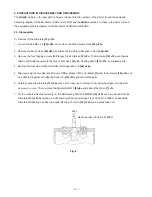
(2) Removal of the Dust Seal
[37] <45>
1. Insert the hooks of the J-204 bearing puller between the commutator and the Dust Seal
[37] <45>
from both
sides, and fix the hooks with the wing bolts.
2. Place the J-204 bearing puller on a supporting jig and push down on the armature shaft with a hand press to
remove the Dust Seal
[37] <45>
together with the Ball Bearing 6000VVCMPS2L
[38] <46>
. Replace the Dust
Seal
[37] <45>
with new one because it is damaged by the removal of the Ball Bearing 6000VVCMPS2L
[38]
<46>
.
(3) Removal of the Stator Ass'y
[16] <16>
1. After removing the Armature
[13] <13>
, disconnect the internal wires connected to the Brush Holders
[47]
<55>
and the Switch
[50] <59>
.
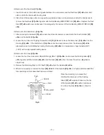
2. Loosen the two Hex. Hd. Tapping Screws D5 x 60
[15] <15>
and remove the Stator Ass'y
[16] <16>
from the
Housing
[40] <48>
. If the Stator Ass'y
[16] <16>
cannot be easily removed from the Housing
[40] <48>
,
disassembly can be facilitated by heating the Housing
[40] <48>
to a temperature of approximately 60
û
C
(140
û
F) with an appropriate heating device.
(4) Removal of the Gear
[20] <20>
1. Loosen the four Hex. Socket Hd. Bolts (W/Flange) M5 x 16
[28] <28>
, and remove the Packing Gland
[27]
<27>
together with the Spindle
[25] <25>
and the Gear
[20] <20>
from the Gear Cover Ass'y
[5] <5>
in a
single body.
2. Remove the Retaining Ring for D12 Shaft
[19] <19>
from the Spindle
[25] <25>
.
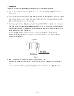
3. When it is necessary to remove the Gear
[20] <20>
from the Spindle
[25] <25>
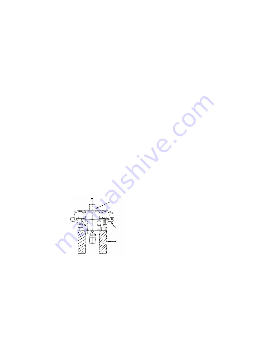
, it is highly recommended that
the special repair tools described below are utilized.
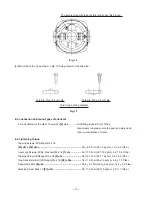
Fig. 9
Sleeve
Packing gland
Spindle
Push
Gear
Place the assembly on a sleeve that
matches the dimension of the Packing
Gland
[27] <27>
and push down on the top
of the Spindle
[25] <25>
with a hand press
to remove the Gear
[20] <20>
as shown in
Fig. 9.
Summary of Contents for G 18SR
Page 34: ......


