background image

--- 8 ---

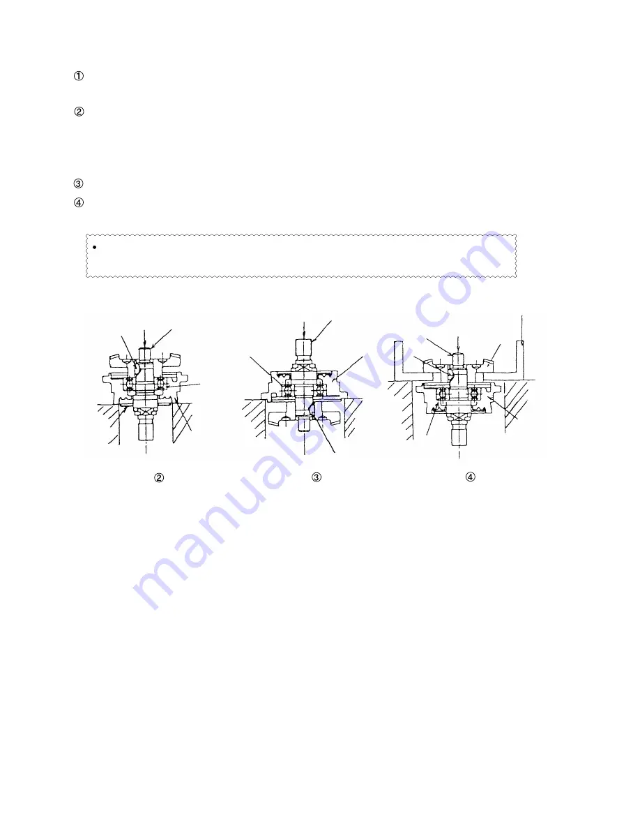
(4) Disassembly of the gear (Fig. 3)

Loosen the Seal Lock Screw (W/Sp. Washer) M4 x 12 [23] fixing the Packing Gland [22], and remove the

Packing Gland [22] from the Gear Cover Ass'y [3].

Support the button of the Packing Gland [22] with a jig, and push down on the upper portion of the Spindle

M10 x P1.5 [25] with a hand press until the end surface of the Woodruff Key 2.5 x 8 [24] contacts the Ball

Bearing 6001VVCMPS2L [20] and the Spindle M10 x P1.5 [25] cannot be pushed down any more.  Be

careful not to deform the Fringer [26].

Turn the Packing Gland [22] upside down and fix it, then push down the Spindle M10 x P1.5 [25].

Insert the gear puller J-128 (use of a steel plate is permitted as a substitute) between the Gear [17]

and the Packing Gland [22], and push down the Spindle M10 x P1.5 [25] with a hand press to remove it.

[25]

[24]

[26]

Fig. 3

Replace the Ball Bearing 6001VVCMPS2L [20] with new one every time the Gear is disassembled

because the force to pull out the Gear is applied to the Ball Bearing 6001VVCMPS2L [20].

[20]

[25]

[20]

[22]

Push

Push

Push

[24]

[22]

[20]

[25]

[22]

[17]

Step

Step

Step

Gear puller J-128
(steel plate)

Summary of Contents for G 10SF3

Page 1: ...POWER TOOLS TECHNICAL DATA AND SERVICE MANUAL DISC GRINDER G 10SF3 SPECIFICATIONS AND PARTS ARE SUBJECT TO CHANGE FOR IMPROVEMENT LIST No E243 Aug 2001 G MODEL G 10SF3 ...

Page 2: ...AL DATA AND SERVICE MANUAL a symbol s is are used in the place of company name s and model name s of our competitor s The symbol s utilized here is are as follows Symbols Utilized Competitors Company Name Model Name MAKITA 9523NB C ...

Page 3: ...emperature Rise 5 7 PRECAUTIONS IN SALES PROMOTION 6 7 1 Handling Instructions 6 7 2 Caution Plate For China only 6 7 3 Precautions on Usage 6 8 PRECAUTIONS IN DISASSEMBLY AND REASSEMBLY 7 8 1 Disassembly 7 8 2 Reassembly 9 8 3 Lubrication Points and Types of Lubricant 11 8 4 Tightening Torque 11 8 5 Wiring Diagram 11 8 6 Insulation Tests 12 8 7 No load Current Value 12 9 STANDARD REPAIR TIME UNIT...

Page 4: ...ficiency of the motor The components of the Model G 10SF3 are the same as those of the Model G 10SF2 except the enclosure and the wiring components 3 APPLICATIONS Removal of casting fin and finishing of various types of steel bronze aluminum and other metallic materials and castings Grinding of welded sections or sections cut by acetylene torch Grinding of slate brick marble and similar materials ...

Page 5: ... sucking dust and fine gravel into the machine G 10SF3 Comparison of wear resistance of armature coils when dust and fine gravel are sucked into the machines Comparison of air vents near the commutator Smaller air vent is provided near the commutator Two air vents are provided near the commutator G 10SF2 100 40 100 G10SF3 G10SF2 50 C 10 13 5 0 60 ...

Page 6: ...itch Weight Net 1 Gross Packaging Standard accessories 2 Depressed center wheel Outer dia 100 mm 4 1 Wrench 1 Voltage current and power input 12 000 min AC single phase commutator motor Housing tail cover Gear cover Inner cover packing gland Glassfiber reinforced polycarbonate resin Green Aluminum alloy die casting Metallic silver Aluminum alloy die casting Voltage V Current A Power input W 220 56...

Page 7: ... output W L mm Dimensions W mm H mm P mm Weight kg Actual weight Type of switch 6 COMPARISONS WITH SIMILAR PRODUCTS 6 1 Specification Comparisons G 10SF2 100 12 000 540 330 610 254 67 60 200 1 4 1 5 Snap 100 11 000 540 290 620 256 81 70 195 1 4 1 5 Slide C L H W P Perimeter Weight excludes cord depressed center wheel wheel nut wheel washer and wheel guard ...

Page 8: ...ation speed and stator coil temperature rise Figure 1 indicates the followings The motor speed of the Model G 10SF3 is higher than that of C at the same torque This means that the working efficiency of the Model G 10SF3 is superior to C Model G 10SF2 is also superior to C The stator coil temperature rise of the Model G 10SF3 is lower than the Model G 10SF2 thanks to the improved cooling mechanism ...

Page 9: ...f the tool by the customer Salespersons must be thoroughly familiar with the contents of the Handling Instructions to be able to offer appropriate guidance to the customer during sales promotion 7 2 Caution Plate For China only The following caution is listed on the Name Plate attached to the main body of each tool 7 3 Precautions on Usage Instruct the customer to pay particular attention to the t...

Page 10: ... of the stator Remove the Armature 220 V 9 and loosen the Tapping Screw W Flange D4 x 25 Black 48 to remove Tail Cover B 47 Loosen the Machine Screw W Washer M3 5 x 6 49 that secures the internal wire of the Cord 51 to the Switch 50 and also the screw on the cord side of the Pillar Terminal 43 Remove the two internal wires from the Cord 51 Remove the Tapping Screw W Flange D4 x 40 38 and the Tappi...

Page 11: ...cannot be pushed down any more Be careful not to deform the Fringer 26 Turn the Packing Gland 22 upside down and fix it then push down the Spindle M10 x P1 5 25 Insert the gear puller J 128 use of a steel plate is permitted as a substitute between the Gear 17 and the Packing Gland 22 and push down the Spindle M10 x P1 5 25 with a hand press to remove it 25 24 26 Fig 3 Replace the Ball Bearing 6001...

Page 12: ...of the Dust Seal 15 contacts against the end surface of the Armature 220 V 9 and make sure that Dust Seal 15 cannot be turned freely by hand Keep the end face of the armature shaft approximately 0 2 mm reference distance inward of the end face of the Ball Bearing 608VVC2PS2L 7 See Fig 5 The Dust Seal 15 is an important element for improved dust protection of the Ball Bearing 608VVC2PS2L 7 Be sure ...

Page 13: ... the Internal Wire 85L 13 between the housing ribs securely 4 pcs Brush Holder 41 Connect the terminal securely without folding Fit the internal wire of the Cord 51 between the ribs Fit each internal wire between the ribs ...

Page 14: ...l Grease No 2 Unilube No 00 Code No 939302 and turbine oil Mixture ratio 1 1 weight ratio 8 4 Tightening Torque D4 Tapping Screws 10 37 38 48 2 0 0 5 N m 20 5 kgf cm 1 5 0 4 fb lbs M4 Slotted Hd Tapping Screw Seal Lock 6 1 8 0 4 N m 18 4 kgf cm 1 3 0 3 fb lbs M4 Seal Lock Screws W Sp Washer 18 23 1 8 0 4 N m 18 4 kgf cm 1 3 0 3 fb lbs D5 Tapping Screw 1 2 9 0 5 N m 30 5 kgf cm 2 2 0 4 fb lbs M5 Ma...

Page 15: ...and conduct a dielectric strength test Insulation resistance 7 M Ω or more with 500 V DC Megohm Tester Dielectric strength test AC 4 000 V 1 minute with no abnormalities 8 7 No load Current Value After no load running for 30 minutes the no load current value should be as follows Voltage V Current A max 220 1 1 ...

Page 16: ...Button Gear Cover Ass y Lock Pin Gear 60 min 50 Bearing Cover B Ball Bearing 6001VVCMPS2L Felt Packing Packing Gland Spindle Fringer Wheel Guard Ass y Switch Cord Tail Cover A Tail Cover B Pinion Ball Bearing 608VVC2PS2L x 2 Inner Cover Armature Dust Seal General Assembly G 10SF3 Housing Stator ...

Page 17: ...PARTS LIST LIST NO DISC GRINDER Model G 10SF3 2001 8 10 E1 E243 1 2 3 4 5 6 7 8 10 11 12 9 13 13 14 15 7 16 17 18 19 20 21 22 23 24 25 26 27 28 29 30 31 32 34 35 36 37 38 40 41 42 43 44 45 46 47 48 49 50 51 501 33 39 ...

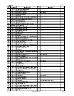
Page 18: ...23 307 127 SEAL LOCK SCREW W SP WASHER M4X12 4 24 940 220 WOODRUFF KEY 2 5X8 1 25 302 046 SPINDLE M10XP1 5 1 26 301 945 FRINGER 1 27 308 386 MACHINE SCREW W SP WASHER M5X16 BLACK 2 28 301 949 SET PLATE 1 29 301 948 WHEEL GUARD ASS Y 1 INCLUD 27 28 30 310 787 WHEEL WASHER 1 31 316 820 D C WHEELS 100MMX4T A36Q 25 PCS 1 32 314 437 WHEEL NUT C 1 33 301 938 GEAR AND PINION ASS Y 1 INCLUD 5 17 34 320 27...

Page 19: ... ALTERNATIVE PARTS 3 ITEM NO CODE NO DESCRIPTION REMARKS NO USED PARTS 51 500 237Z CORD 1 FOR HKG G 10SF3 8 01 ...

Page 20: ... ALTERNATIVE PARTS 4 ITEM NO CODE NO DESCRIPTION REMARKS NO USED STANDARD ACCESSORIES G 10SF3 501 313 933 WRENCH 1 Printed in Japan 010810N 8 01 ...

Page 21: ......

Reviews: