13
CONNECTING PERIPHERAL EQUIPMENT
Caution!
• Be sure to disconnect the plug from the power
outlet before connecting/disconnecting cables.
Also, read the manual of the equipment to be
connected.
• Be careful not to confuse the input terminal with
the output terminal when connecting cables.
Accidentally reversing cables connected to the
input and output terminals may cause
malfunctions and the other problems.
• Do not use any cable that has a damaged or
deformed terminal. Using such cables may cause
malfunctions.
Tips
• Wait for the interactive monitor to search and
find the source automatically when the interactive
monitor is used for the first time. The screen is
adjusted automatically.
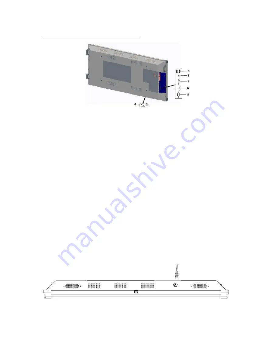
4. AC Input Terminal
• Use only the power cord supplied with the
interactive monitor.
5. RS-232 Input Terminal
• You can control the interactive monitor from a
PC by connecting a commercially available RS-232
straight cable between these terminals and the PC.
6. Line In/Out Terminals
• Line In: Connect an external audio device to
record or manipulate the incoming sound data.
• Line Out: Connect to an external amplifier.
7. VGA Input Terminal
• Use a commercially available VGA cable
• Use Source Select button (
11 Source Select
Button
) to set mode as a VGA.
8. USB B-Type Input Terminal
• Use USB B-Type connector for the external PC
and touch screen connection.
9. HDMI input terminal x 2
• Use a commercially available HDMI cable
(conforming to the HDMI standard).
• Use Source Select button (
11 Source Select
Button
) to set mode as an HDMI.
Tips
• The length of the signal cables or surrounding
environment may affect the image quality.
Connecting the Power Cord
Caution!
• Use only the power cord supplied with the interactive monitor.
• Plug the power cord (supplied) into the AC input terminal.
Summary of Contents for FHD7510
Page 1: ...75 190cm INTERACTIVE MONITOR FHD7510PC FHD7510 LED ...
Page 11: ...10 SUPPLIED COMPONENTS Remote Controller CR2025 Battery Power Cord IB ...
Page 22: ...21 RS 232 COMMAND TABLE ...
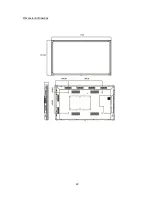
Page 29: ...28 Dimensional Drawings ...
Page 32: ...31 ASSEMBLY INSTRUCTION FOR INTERACTIVE MONITOR WALL MOUNT 1000 519 681 200 200 600 ...


