37
PJ-LC9(C12H)
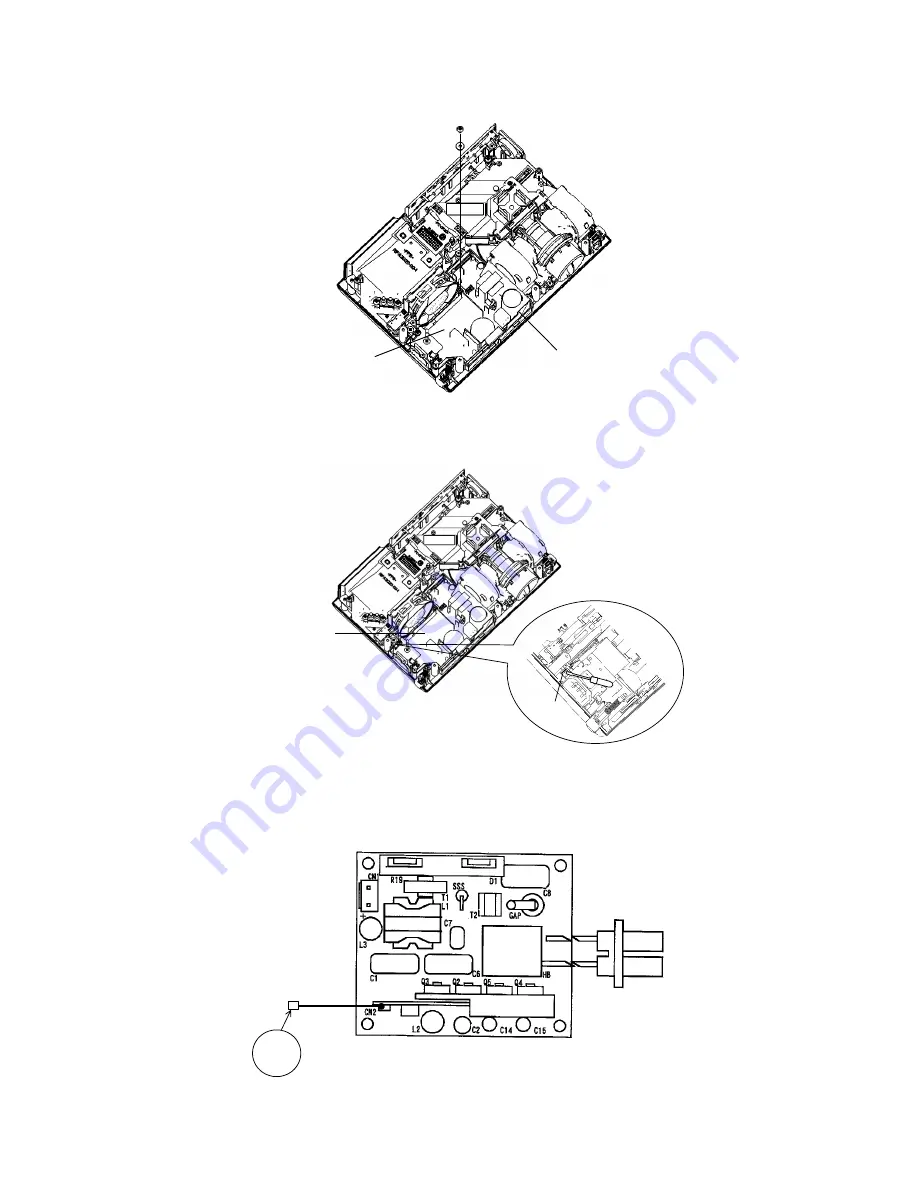
4. Cautions When Removing The Power Unit (BALLAST)
When removing the cable (CNBAR) connected to Power Unit (BALLAST), there is danger of damaging the
small PWB connecting cables.
Disconnect the CNBAR from connector CN2,
while pressing the sub-board
(to prevent the stress on the sub-board).
Power Unit (BALLAST)
CNBAR
(2) Take the Power Sheet off, and then unscrew a screw with a plastic washer.
Screw
POWER UNIT
(CIRCUIT)
Power Sheet
In removing POWER BOARD(CIRCUIT) from the bottom case assembly, use flat screw driver or fine tool to
unclip the holder with the arrow shown below.
Clip
POWER UNIT(CIRCUIT)
Summary of Contents for EDPJ32
Page 34: ...34 PJ LC9 C12H ...
Page 51: ...51 PJ LC9 C12H 12 Connector connection diagram Connector connection diagram CN103 ...
Page 55: ...1 2 3 4 5 6 6 1 2 3 4 5 D G F E C B A PWB assembly MAIN 1 C12H ...
Page 56: ...1 2 3 4 5 6 6 1 2 3 4 5 D G F E C B A PWB assembly MAIN 2 C12H ...
Page 57: ...1 2 3 4 5 6 6 1 2 3 4 5 D G F E C B A PWB assembly MAIN 3 C12H ...
Page 58: ...1 2 3 4 5 6 6 1 2 3 4 5 D G F E C B A PWB assembly MAIN 4 C12H ...
Page 59: ...1 2 3 4 5 6 6 1 2 3 4 5 D G F E C B A PWB assembly MAIN 5 C12H ...
Page 60: ...1 2 3 4 5 6 6 1 2 3 4 5 D G F E C B A PWB assembly MAIN 6 C12H ...
Page 61: ...1 2 3 4 5 6 6 1 2 3 4 5 D G F E C B A PWB assembly MAIN 7 C12H ...
Page 62: ...1 2 3 4 5 6 6 1 2 3 4 5 D G F E C B A PWB assembly MAIN 8 C12H ...
Page 63: ...1 2 3 4 5 6 6 1 2 3 4 5 D G F E C B A PWB assembly MAIN 9 C12H ...
Page 64: ...1 2 3 4 5 6 6 1 2 3 4 5 D G F E C B A PWB assembly MAIN 10 C12H ...
Page 65: ...1 2 3 4 5 6 6 1 2 3 4 5 D G F E C B A PWB assembly MAIN 11 C12H ...
Page 66: ...MEMO ...
Page 68: ...QR65311 Digital Media Division Printed in Japan JE PJ LC9 YK No 0556 ...


